Anchor
An Anchor is a support that restrains the pipe movement at a node in the three translational and the three rotational directions (i.e., restrains the node in all six degrees of freedom). In a physical piping system, this node may be on an anchor block or a foundation, or a location where the piping system ties into a wall or a large piece of equipment like a pump.
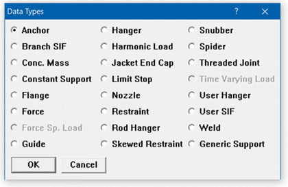
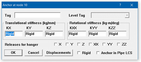
An Anchor is input by typing “A” in the Data column or selecting Anchor from the Data Types dialog. A rigid anchor is entered (i.e., an anchor with rigid stiffnesses in all six degrees of freedom) by default. To change the default, edit the anchor by double-clicking on the anchor or pressing Ctrl+D in the row that has the anchor. An Anchor dialog is shown next.
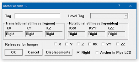
Uncheck the “Rigid” checkbox to make the anchor non-rigid (i.e., a flexible anchor), and enter numerical values for stiffnesses in the six degrees of freedom.
The stiffness for a degree of freedom may be rigid (specified by typing the letter “r” in the stiffness field), or some value. If it is input as 0.0 or with a small number, then there is no stiffness in that degree of freedom, i.e., the pipe is free to move in that degree of freedom. Internally, the rigid stiffness value is set to 1×10¹² (lb./inch) for translational stiffness and 1×10¹² (inch-lb./radian) for rotational stiffness.
Note:
When stiffness is input as 0 in any of the degrees of freedom, then CAEPIPE will leave the corresponding Force or Moment column as BLANK in Support Load results. Hence, it is recommended to input a very small number, say 1E-30, as stiffness instead of 0, when there is no stiffness in any of the degrees of freedom. When stiffness is input as 1E-30, then the corresponding Force or Moment column will be output as 0 in Support Load results.
Releases for Hanger Selection
These releases apply only during the automatic selection of a hanger by CAEPIPE. If you checked any of the Release check boxes, the pipe is assumed to be free in that released degree of freedom during the automatic hanger selection by CAEPIPE. You may release any combination of degrees of freedom at a hanger node during such automatic hanger selection. This feature is useful when hangers are located near equipment, where you want the hangers to carry most of the weight load and thus reduce the load acting on the nearby equipment. CAEPIPE, during hot load calculation (preliminary sustained load case) in hanger design, releases the anchors (if you selected any of the Release checkboxes) so that the weight loads are taken by the hangers rather than by the anchors (which represent the equipment).
After the hot load calculation, CAEPIPE restores the original values of stiffnesses to the released anchors before continuing analysis. Release anchors when they are (typically) within four (4) pipe diameters away from the nearest hangers.
You may release any combination of translations or rotations. Typically, either the vertical translation or all translations and rotations are released. To release the Anchor in a particular degree of freedom, check the corresponding checkbox.
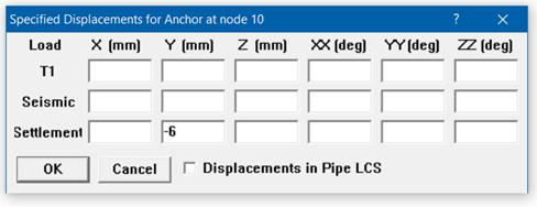
.Displacements.
The dialog for Specified Displacements at an Anchor Support is shown below. Displacement fields will be enabled or disabled automatically depending upon the load cases defined.
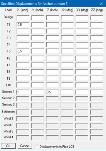
At an anchor, three types of translations and/or rotations in the global X, Y and Z directions may be specified as listed below.
1. Thermal displacements (up to 10 sets can be specified, one each for thermal loads T1 through T10). Applied only to the corresponding Expansion and Operating load cases.
2. Seismic displacements (Seismic 1, 2 and 3) are available for all codes. Solved as a separate internal load case, the results of which are added absolutely to the corresponding static seismic load cases. For response spectrum analysis, only results from Seismic 1 displacements are added absolutely to the response spectrum load.
3. Wind displacements (up to 4 sets can be specified, one each for each of the Wind loads Wind 1 through Wind 4). Applied to the corresponding Wind load cases.
4. For Piping Code = NONE, Specified Displacement results for Seismic 1 and Wind 1 load cases are “Algebraically” added to the results from all other load cases.
You may specify a displacement only if you also specify a corresponding non-zero or rigid stiffness in that degree of freedom, i.e., the corresponding stiffness should not be left blank.
Check “Displacements in LCS” if you want to enter anchor movements in the local coordinate system. These local movements are transformed into the global coordinate system and displayed in results.
For certain piping codes (ASME B31.1, ASME Section III Class 2, ASME NM.1, RCC-M, EN 13941 and EN 13480), an anchor settlement, which is a single non-repeated anchor movement (e.g., due to settlement of foundation), may be specified. This is applied to the Settlement load case. For those codes that do not have a provision for settlement (like B31.3), specify the anchor settlement as a thermal displacement (which tends to be a conservative approach) for one of the temperature load and define that temperature as equal to reference temperature. For EN13941-1, specified displacements input as Settlement are included in Sustained load case.
Anchor in Local Coordinate System (LCS)
Check the box “Anchor in LCS” if you want to orient the anchor along a skewed line using its local coordinate system (LCS), which also aids you in specifying Displacements in LCS. Notice the naming convention changes (KXX changes to kxx, X changes to x, and so on).
Note:
1. Pressure Thrust (End-cap Force) of Pressure P x Inner Area (A) of pipe is not included in the Support Loads for Anchors displayed by CAEPIPE at this time. Since CAEPIPE’s results for numerous problems compare well with the results from other third-party software, it confirms that the other stress programs are also not including the Pressure Thrust (End-cap Force) of pipe in the Anchor Loads at this time. Refer to the Verification Manual supplied with CAEPIPE for comparison of results with other stress programs.
If you wish to include the effect of Pressure Thrust (End-cap force) due to internal pressure in your piping on the Anchor loads, then you will have to compute the same manually (= P x A) and input it as an external force at the Anchor Nodes using the Force data type available with CAEPIPE. Please choose the option “Add to W+P” in the Force data type dialog. By doing so, the End-cap force (= P x A) will be included in all relevant load cases and combinations of CAEPIPE. Of course, when the “None” code is selected under Options>Analysis> Code, this End-cap force is included in the only case of “Static”.
2. At an Anchor defined in space to which a pipe support is attached, a “dummy” element has to be added. This additional element should be defined such that the Local Coordinate System for this element should be the same as the Local Coordinate System of the attached Anchor.
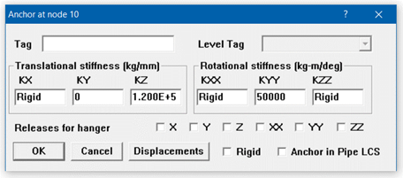
Example 1: Flexible Anchor
Nodes on most large equipment are modeled as rigid anchors. If you need to specify a non-rigid (i.e., flexible) anchor (for example at a nozzle to include vessel flexibility), you can input those stiffnesses by editing the anchor.
Double click on the anchor to show the anchor dialog.
By default the anchor has all stiffnesses rigid, no releases for hanger selection and no specified displacements. The stiffness fields are grayed, i.e., non-editable and the Rigid checkbox is checked. Click on the Rigid checkbox to uncheck it. The stiffness fields now become editable.
Type in the required stiffness values and press Enter or click on OK. The anchor definition shown in the next figure is now modified to be a flexible anchor.
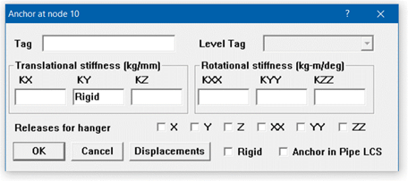
Example 2: Rigid Vertical Support with Foundation Settlement
Assume that you need to model a vertical support on a foundation that has settled using ASME Section III Class 2 (1980) code for code compliance.
Vertical settlement (–Y) = 6 inches.
First, set the piping code to ASME Section III, which has a provision for Settlement load case, using the menu Options > Analysis > Code in the Layout window.
Next, create a rigid vertical support at the required node. Press “a” in the Data field to input a default anchor.
Next, edit the anchor so that it acts as a vertical support only, by modifying the stiffnesses similar to Example 1 so that only a Rigid stiffness KY in the Y direction remains.
Now the anchor is modified to act as a Vertical 2-way rigid support. Click on the Displacements button and type in –6 (inch) for Settlement under Y. You could also input thermal and seismic displacements if required.
The anchor is now modified to be a rigid vertical support with a specified settlement displacement.
Example 3: Anchor Release during Hanger Design
CAEPIPE lets you model equipment nozzles as anchors. Assume that you had one on a turbine, as shown above, and that you have placed a hanger nearby. The main purpose of this hanger would be to carry most of the piping weight that would have been imposed on the nearby turbine nozzle if not for the hanger. To let CAEPIPE do that, you will have to release all six degrees of freedom of the Anchor during hanger design so that the hanger will be designed to carry most of the piping weight.
First, enter an anchor for the node and then double click on it to edit it.
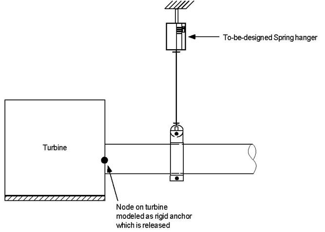
Click on the checkboxes for Releases for hanger selection in the required directions (X, Y, Z, XX, YY, ZZ). The anchor will be released in the specified directions during hanger design.
CAEPIPE restores the anchor to its original state (of no releases) after completing the preliminary hot load calculation during hanger design. Refer to the section on Hanger Design Procedure for further details.