Fiber Reinforced Plastic Piping (FRP)
FRP piping has gained wide acceptance in many industries due to its lightweight nature, superior corrosion resistance, temperature capabilities and mechanical strength. Several manufacturers produce different types of FRP pipes and fittings and provide technical assistance to their customers on design matters through installation. You can model FRP materials in CAEPIPE and have it calculate deflections, forces, moments and stresses.
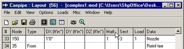
To define the FRP material, click on “Matl” in the header row in the Layout window.
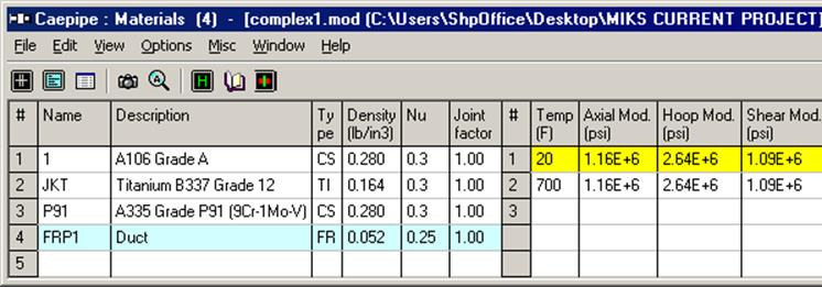
In the Material List window that is shown, double click on an empty row to input a new material or on a material description to edit the material properties.
The Material dialog will be shown.
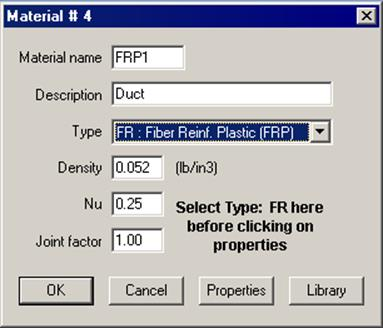
The material name can be up to five alpha-numeric characters. Enter description and density. You need to select “FR: Fiber Reinf. Plastic (FRP)” from the Type drop-down combo box before you click on the Properties button. Poisson's ratio (Nu) is a measure of the Poisson effect, the phenomenon in which a material tends to expand in directions perpendicular to the direction of compression. Conversely, if the material is stretched rather than compressed, it usually tends to contract in the directions transverse to the direction of stretching.
When you click on the Properties button, you are shown the table below where you enter temperature-dependent properties. Additionally, you can define the Axial and Torsional allowable stresses so that CAEPIPE can use them to compare with calculated stresses under the FRP "Sorted Stresses” results.
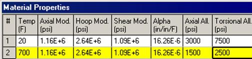
FRP Material Moduli
CAEPIPE requires three moduli for a FRP material:
Axial or Longitudinal (this is the most important one)
Hoop (used in Bourdon effect calculations). If this modulus is not available, use axial modulus.
Shear or Torsional. If this modulus is not available, use engineering judgment in specifying 1/2 of axial modulus or a similar value. Note that a high modulus will result in high stresses, and a low modulus will result in high deflections.
For FRP bends, a Flexibility factor of 1.0 is used unless you override it by specifying a Flexibility factor inside the bend dialog. Also for FRP bends, CAEPIPE uses a default SIF of 2.3. You can override this too by specifying User-SIFs at the bend end nodes (A and B nodes).
The stiffness matrix for an FRP material is formulated in the following manner:
The stiffness matrix for a pipe is calculated using the following terms:
Axial term = L / EA
Shear term = shape factor x L / GA
Bending term = L / EI
Torsion term = L / 2GI
where L = length, A = area, I = moment of inertia
E = Elastic modulus, G = shear modulus
For an isotropic material,
G = E / 2(1 +  )
)
where = Poisson’s ratio,
For a FRP material, however,
E = axial modulus and G is independently specified (i.e., it is not calculated using E and ).
The hoop modulus and FRP Poisson’s ratio are only used in Bourdon effect calculation where,
Poisson’s ratio used = FRP Poisson’s ratio input x (axial modulus / hoop modulus)
Results
CAEPIPE calculates deflections, forces, moments and stresses. Each item can be seen under the respective title in Results. FRP element stresses can be seen, sorted or unsorted. These FRP stresses are computed as per the formulae given in Section titled “Piping Code Compliance” in the Code Compliance Manual.
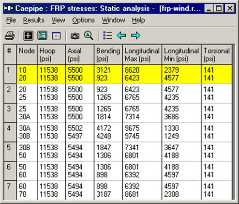
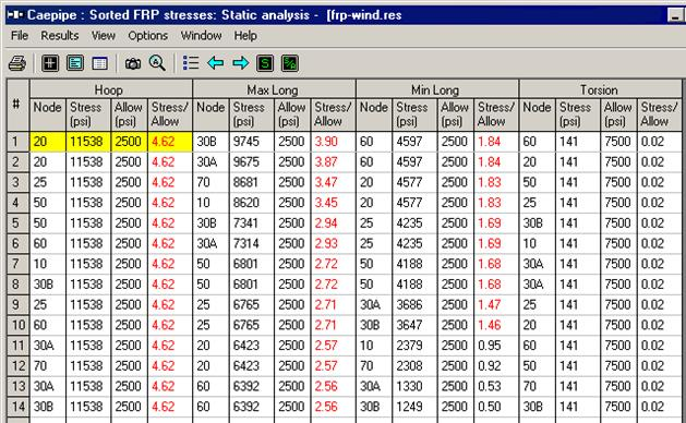
Axial and Torsional allowable may be entered under material properties so that they can be used to compare against calculated stresses in “Sorted FRP Stresses.” Forces, Stresses and Sorted stresses for FRP piping may be printed to a .CSV file (spreadsheet-compatible).
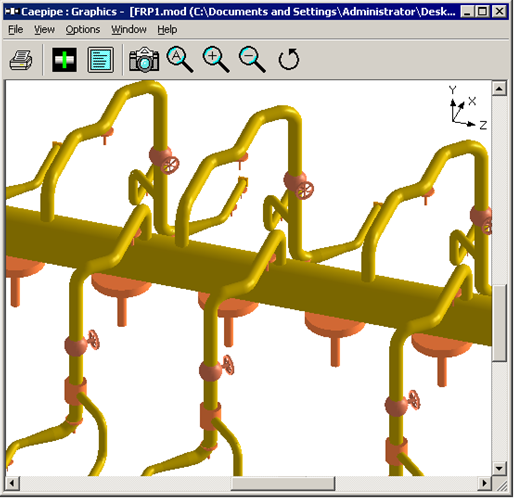
CAEPIPE renders FRP piping in golden color.