Flange
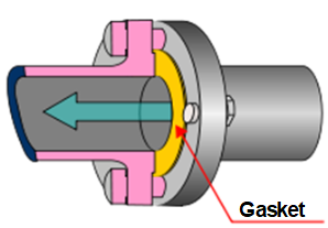
A flange is a method of connecting pipes, valves, pumps and other equipment to form a piping system. It also provides easy access for cleaning, inspection or modification. Flanges are usually welded or screwed. Flanged joints are made by bolting together two flanges with a gasket between them to provide a seal. The material of a flange, is basically set during the choice of the pipe, in most cases, a flange is of the same material as the pipe. There are many different flange standards being followed worldwide. To allow easy functionality and inter-changeability, these are designed to have standardized dimensions. Common world standards include ASA/ANSI/ASME (USA), PN/DIN (European), BS10 (British/Australian), and JIS/KS (Japanese/Korean).
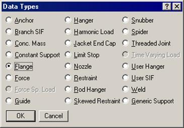
A flange is input by typing “fl” in the Data column or selecting “Flange” from the Data Types dialog. If flanges are located at the bend end nodes (A, B nodes), or jacket bend nodes (C, D nodes), the bend flexibility and SIF are internally modified in CAEPIPE.
The Flange dialog is shown.
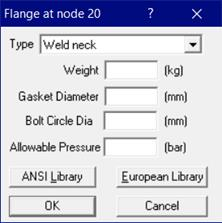
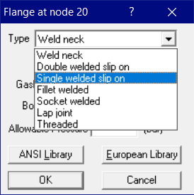
Several flange types are available – weld neck, socket welded, threaded, lap joint, etc. Use the Type drop-down combo box to select one.
Weight
The weight you provide should be the total weight of flanges, i.e., if there are two flanges the weight should be the weight of two flanges. Weight is to be input in lbf or kgf and NOT in mass units. Whenever mass is required for a calculation as in the case of forming Mass matrix for dynamic analysis, or in calculating inertia force as (mass x acceleration) for static seismic analysis, CAEPIPE internally computes the mass to be equal to (weight / g-value).
Gasket Diameter
The gasket diameter is used in calculating equivalent flange pressure in the flange report.
As stated in Section titled “Flange Report” below, Gasket Diameter (G) required is the “diameter at location of gasket load reaction”. This Gasket Diameter (G) can be calculated as detailed in “Flange Report” section.
Bolt Circle Dia
The bolt circle diameter is used in calculating equivalent flange pressure as per EN 13480-3. See the sub-section “Flange Report” below for details.
CAEPIPE provides an approximation for the tendency of a flange to leak by calculating an “equivalent flange pressure” and comparing it to the (user-input) allowable pressure for the flange in the flange report. Often, the allowable pressure may be conservatively set to the flange rating. The allowable pressure can be taken from B16.5 (or a similar standard) for the flange class, material, pressure and temperature.
The temperature-pressure ratings provided in ASME/ANSI B16.5 are computed using the formula given in para. D2.1 of Annex D of ASME/ANSI B16.5 (given below). The values thus obtained are listed in a tabular form for all materials at different flange ratings.
PT = (Pr x SI) / 8750 <= Pc
where,
Pc = Ceiling pressure as specified in D3 of Annex D at temperature.
PT = Rated working pressure in psig for specified material at temperature.
Pr = Pressure rating as per Class in Psig.
SI = Selected stress in Psig for specified material at temperature.
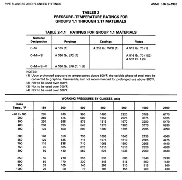
For example, from the values shown in Table 2.-1.1 of ASME B16.5 (1998) (shown above), for a 300# carbon steel flange with Material A105, the allowable pressure is 740 psig at 100°F. This is calculated as detailed below.
Allowable Stress = Minimum (60% of Min. Yield, 1.25 x Allowable Stress at Temperature) as per para. D2.2 of Annex D of ASME B16.5 (1998).
Accordingly, Allowable Stress (SI) from ASME Boiler and Pressure Vessel Code, Section II, Part D for A105 at Temperature 100 deg. F = Minimum(60% of Min. Yield, 1.25 x Allowable Stress at Temp) = Minimum(60% of 36000, 1.25 x 20000) = Minimum(21600, 25000) = 21600 psi
Pressure rating (Pr) = 300 #
So, rated working pressure (PT) = (21600 x 300) / 8750 = 740 psi (same as the value shown in the snapshot).
Flange Library
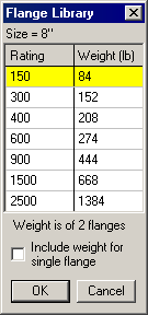
You may access the flange library by clicking on the Library button of the flange dialog. The default weight in the Flange Library is for two Flanges. However, each library dialog has an option to include weight for a single flange. See checkbox in the Flange library dialog below to include weight for a single flange.
ANSI Library
European Library
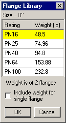
The default weight in the library is the weight of two weld neck flanges (including bolts).
Flange Report
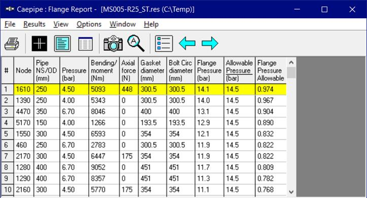
CAEPIPE lists every flange in a model in the flange report. The “Flange Pressure” is an equivalent pressure calculated from the actual pressure in the piping element, the bending moment and the axial force on the flange from the operating case(s), as follows:
When the option “EN 13480-3 (2024)” is selected through Layout Window > Options > Analysis > Misc, then equivalent pressure is calculated in accordance with Eq. 6.6.2-1 of EN 13480-3 (2024) as given below.
where,
Bending Moment = resulting bending moment
Axial force is included in the calculation only when it is Tensile (+ve) as stated in para. 6.6.2 of EN 13480-3 (2024) code.
C = Diameter of the bolt circle. “Gasket Diameter G” input at Flange dialog is used internally as “C” when the field “Bolt Circle Diameter” is left BLANK.
On the other hand, when the option “ASME Class 2 (2023)” is selected through Layout Window > Options > Analysis > Misc, then equivalent pressure is calculated in accordance with NC.3658.3 of ASME Section III Class 2 (2023) as given below.
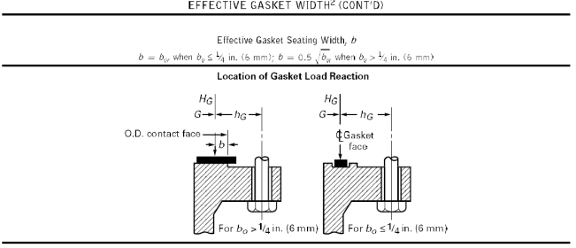
The Gasket diameter is at the gasket loading location (if it is not input, it is conservatively assumed to be the internal diameter of the pipe).“Gasket loading location” is the location where the gasket load reaction is acting. As per ASME Sec. VIII Division 1, “G” is the diameter at location of gasket load reaction and can be calculated as follows. See snap shots shown below for details.
G = mean diameter of gasket contact face, inches, when b0<= ¼ inches or G = outside diameter of gasket contact face - 2b, inches, when b0> ¼ inches.
Mfs = Maximum (Resultant Bending Moment, Torsional Moment)
where,
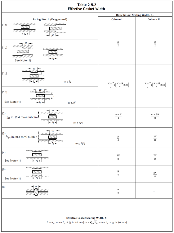
b = effective gasket or joint-contact-surface seating width, inches.
b0 = basic gasket seating width, inches.
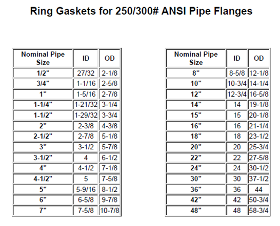
In the absence of seating width data, G can be taken as the mean diameter[= (ID + OD) / 2]. For example, as per the snap shot shown below, the mean diameter G for the "Ring Gaskets for 250/300# ANSI Pipe Flanges" for 8” is 10.375” [= (8.625” + 12.125”) / 2].
The computed equivalent flange pressure is compared with the flange allowable pressure.
If you have input more than one temperature load, the flange equivalent pressure is calculated for all the applicable operating load cases, the worst of which is reported in the Flange report.
A flange report is generated even when no piping code is chosen. The flange report is shown in the results.
Suggestions for dealing with high equivalent flange pressure to allowable ratios
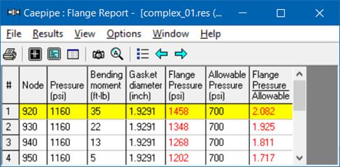
The Flange report in the CAEPIPE results window shows the loads at each flange location for the worst operating load case (W+P+T).
The “equivalent” flange pressure is the sum of two terms from the flange equation as shown above. The last column in the Flange report shows a ratio of this equivalent flange pressure to a user-input allowable pressure. This ratio is flagged in red when greater than 1.0.
Ensure that you input an allowable pressure for the flange by looking up B16.5 or a similar code (as a function of Peak Temperature and pressure).
Since a flange is unlikely to fail by collapse, the key idea of the flange report is to “quantify” the tendency of a flange to leak its contents. Engineering judgment will play an important role in interpreting this report.
If the ratio of equivalent flange pressure to allowable pressure is flagged in red, then try to reduce the bending moment at that flange location. Be sure to examine all load cases, but frequently the excessive moments come from the expansion case. If so, consider introducing loops, bends and offsets as required to reduce the bending moments at flange locations for expansion load case(s).If it is practical, move those flanges with high (flange pressure-to-allowable) ratios to piping locations where the bending moments are less.