Guide
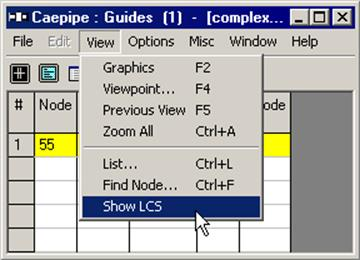
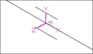
A guide is used in the field to control or direct pipe movement. Likewise, its CAEPIPE equivalent allows axial movement while restraining the pipe against lateral translations (but not rotations). A guide restricts the translational movement normal to its axis, i.e., displacements are restrained in the local y and z directions of the element to which the guide is attached. The Local Coordinate System (LCS) of the guide can be viewed through View > List > Guide and right-click mouse and select the option “Show LCS”.
A guide is input by typing “g” in the Data column or selecting “Guide” from the Data Types dialog.
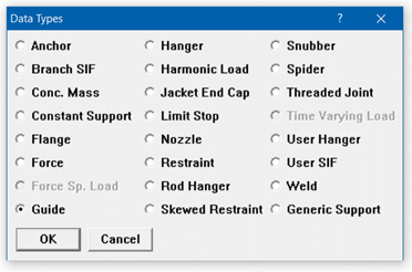
The Guide dialog is shown.
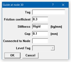
Tag
Tag can be 12 characters long. Tags are useful in identifying a support while modeling, reviewing of reports and in field erection. Tag Name entered in this field is shown in all reports.
Friction Coefficient
When a friction coefficient is entered, a nonlinear analysis is performed. In each iteration, the friction force is calculated which is friction coefficient times the normal force (the vector sum of local y and local z reaction forces). This friction force is applied in the local x direction opposing the axial motion of pipe. The solution converges when the displacement changes by less than 1% between successive iterations.
Stiffness
The default stiffness is rigid which is input by typing “r” or “Rigid” in the Stiffness field. A non-rigid stiffness may be entered by typing the value of the stiffness in the Stiffness field.
Gap
A clearance between the pipe and the guide, if present, may be entered as a Gap. The gap is assumed to be symmetric about the guide axis. This gap must be closed before any restraint forces can develop. If there is no gap, leave this field blank or enter it as 0.0.
Connected to Node
By default the guide is assumed to be connected to a fixed ground point which is not a part of the piping system. A guide can be connected to another node in the piping system by entering the node number in the “Connected to Node” field.
Local Coordinate System (LCS)
A guide’s local x-axis is based on the preceding element. If a preceding element is unavailable, the following element is used to determine the guide’s local x-axis. The local coordinate system (LCS) may be viewed graphically from the Guide List window using the menu: View > Show LCS.
Guide forces in global coordinate system are “Print(ed) to file” (in addition to forces in local coordinate system), accessible from the Print command dialog.