Hanger
Variable spring hangers support the dead-weight of piping while allowing vertical and lateral thermal movement from the installed to the operating condition. CAEPIPE assumes a spring hanger to always act in the vertical direction.
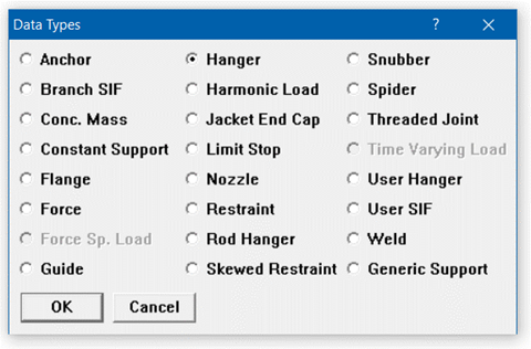
Also called a “To be designed” hanger, it is input by typing “h (Enter)” in the Data column (or typing “Han”) or selecting “Hanger” from the Data Types dialog. The Hanger dialog is shown.
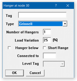
Tag
Tag can be 12 characters long. Tags are useful in identifying a support while modeling, reviewing of reports and in field erection. Tag Name entered in this field is shown in all reports.
The type (i.e., manufacturer) of the hanger can be selected from the drop-down combo box “Type.” The following hanger types are currently available:
|
|
Hanger Types
|
|
|
ABB-PBS
|
Fee & Mason
|
Nordon
|
|
Basic Engineers
|
Flexider (30-60-120)
|
NPS Industries
|
|
Bergen-Paterson
|
Flexider (50-100-200)
|
Piping Services
|
|
Bergen-Paterson (L)
|
Fronek
|
Piping Tech & Products
|
|
BHEL Hyderabad
|
Grinnell
|
Power Piping
|
|
BHEL Trichy
|
Hydra
|
Sanwa Tekki(30-60-120)
|
|
Borrello
|
Lisega
|
Sanwa Tekki(85-170)
|
|
Carpenter & Paterson*
|
Mitsubishi (30-60-120)
|
Sarathi
|
|
Comet
|
Mitsubishi (80-160)
|
Spring Supports
|
|
Corner & Lada
|
Myricks
|
SSG
|
|
Dynax
|
NHK (30-60-120)
|
Gradior
|
|
Elcen
|
NHK (80-160)
|
|
|
|
|
|
*CAEPIPE includes catalog from Carpenter Paterson Ltd. based in England.
Number of Hangers
The number of hangers is the number of separate hangers connected in parallel at this node. The stiffness and load capacity of each hanger are multiplied by the number of hangers to find the effective stiffness and load capacity of all the hanger supports at this node.
Load Variation
The load variation (in percent) is the maximum variation between the cold and hot loads. Typical value is 25%.
Changes the graphical depiction only.
This should be used to specify whether the Hanger is placed below the pipe. Graphical symbol changes accordingly. This selection is valid only for Hanger and User Hanger and neither for Constant Support Hanger nor Rod Hanger.
Short Range
Short range hangers are used if the available space is not enough for installing mid-range hangers. They are considered, however, as a specialty item and generally not used. If a short range hanger is to be designed, check the Short Range check box.
Connected to Node
By default the hanger is connected to a fixed ground point which is not a part of the piping system. A hanger can be connected to another node in the piping system by entering the node number in the “Connected to node” field. This node must be directly above or below the hanger node.
Hanger Design Procedure
1. Calculate Hot Load
Hot load for a variable spring hanger is the actual weight of the pipe (including the weights of content, lining and insulation) being carried by that hanger. To calculate hot load, a preliminary sustained load analysis is performed in which all hanger locations are restrained vertically. If any anchor is to be released (so that the hanger rather than the nearby equipment takes the sustained load), it is released. The reactions at the hanger locations from this preliminary sustained load analysis are the hanger hot loads.
Vertical restraints (applied in step 1) at hanger locations are removed. Released anchors (if any) are restored. A preliminary operating load case analysis is performed. If multiple thermal load cases are specified, only the first thermal load is used for this operating load case. The hot loads (calculated in step 1) are applied as upward forces at the hanger locations. Vertical displacements at the hanger locations obtained from this operating load case analysis are the hanger travels. If limit stops are present, the hot loads are recalculated with the status of the limit stops at the end of the preliminary operating load case. Then the hanger travels are recalculated using the recalculated hot loads.
3. Select Hanger
The hanger is selected from the manufacturer’s catalog based on the hot load and hanger travel. The cold load is calculated as: cold load = hot load + spring rate x hanger travel. The hanger load variation is calculated as: Load Variation = 100 x Spring rate x travel / Hot load. The calculated load variation is checked against specified maximum load variation. The hanger for which both the hot and cold loads are within the hanger’s allowable working range and the load variation is less than the allowed load variation is selected. The hanger is selected such that the hot load is closest to the average of the minimum and maximum loads.
4. Install Hangers
If “Include hanger stiffness” is chosen in the Analysis options: The hanger spring rates are added to the overall stiffness matrix. The hanger cold loads are used in the sustained and operating load cases. If “Do not include hanger stiffness” is chosen in the Analysis options: The hanger spring rates are not added to the overall stiffness matrix. The hanger hot loads are used in the sustained and operating load cases.
For Lisega hangers, size column will report as Hanger Number, Type and Range instead of Hanger Number, Range and Type. For example, hanger having a spring rate of 2.1 N/mm, vertical travel of 30mm with load 440N will be reported as 21D.193 instead of 21D319.
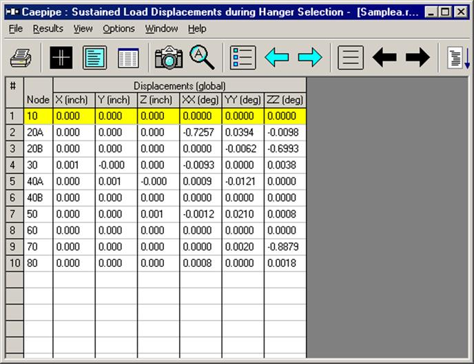
Sustained Displacement during Hanger Selection
An Example Application
Sometimes, rotating equipment vendors (e.g. turbine vendors) require that there be no weight load imposed on the turbine connections after welding/bolting the pipe to the nozzle but prior to plant start-up. This can be accomplished only if the pipe is hung by variable spring hangers like a swing at the nozzle and if the pipe end of such “hung” pipe is almost perfectly aligned with the turbine nozzle prior to welding or bolting that pipe end to the turbine nozzle. In other words, the spring hangers that carry the weight of the “hung” pipe near the nozzle are to be sized and placed such that the resulting displacements (i.e., 3 translations and 3 rotations) at the pipe end are nearly zero, so that the pipe end need not be forcibly deformed in order to weld/bolt it to the turbine nozzle. This, in turn, makes sure that the weight load of the pipe is not imposed on the turbine nozzle prior to plant start-up.
CAEPIPE can be used to perform the above study by carrying out the following steps.
a) During Step 1 of the Hanger Design procedure given above, release all 6 degrees of freedom of the anchor corresponding to that turbine nozzle, so that piping weight load will not be transferred to the nozzle during the initial Sustained load analysis (in which all hangers are pinned, thereby restraining the pipe vertically at the hanger locations).
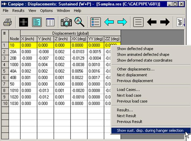
b) Review the preliminary Sustained Load Displacements computed during Hanger Selection via Results > Displacements > Mouse right click > Show sust. disp. during hanger selection. If the Sustained Load translations and rotations at the concerned pipe end are NOT nearly zero, try out different hanger locations till the preliminary Sustained Load displacements at that pipe end are nearly zero.
c) When the Preliminary Sustained Load displacements at the concerned pipe end are nearly zero, the Support Loads at that Nozzle reported by CAEPIPE for Sustained Load case would be close to zero.
In results, the sustained displacements during hanger selection when hangers are pinned can be shown via Results >Displacements>Mouse right click>Show sust. disp. during hanger selection.
And here is the Results Window for sustained displacements during hanger selection after selecting this feature.