Hinge Joint
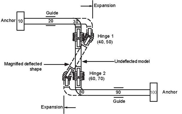
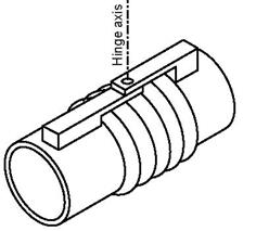 Hinge joint is an expansion joint designed to permit angular rotation in a single plane by use of a pair of pins that pass through plates attached to the expansion joint ends. Hinge joints are used in sets of two or three to absorb pipe movement in one or more directions in a single-plane piping system. A pair of hinge joints, separated by a section of piping, will act together to absorb lateral deflection. Hinge joints are designed to take the full pressure thrust.
The two sides of the hinge joint shown are joined by hinge pins which are along the hinge axis shown in the figure. A hinge is modeled by two nodes, one on each side of the hinge joint. The two nodes of the hinge joint are coincident. So, it is a zero length element, i.e., the “From” and “To” nodes are coincident. Hence, the DX, DY and DZ fields in the Layout window should be left blank.
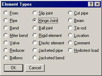
A hinge joint is input by typing “h” in the Type column or selecting “Hinge joint” from the Element Types dialog.
The Hinge joint dialog is shown.
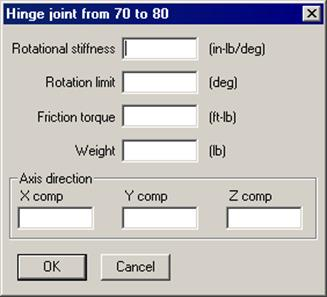
Rotational Stiffness
Also called Angular stiffness. Input the stiffness around the rotational (hinge) axis. The stiffness value may be available from the manufacturer of the hinge joint or from test results. Otherwise engineering judgment may be used. The stiffness values may be left blank. In that case a very small value (1 in-lb/rad.) is used internally to avoid dividing by zero.
Rotation Limit
Rotation limit is an upper limit on the rotation of hinge joint in the plus or minus directions. Rotation limit of 0.0 (zero) means it is unable to rotate (i.e., it is rigid). Rotation limit of “None” or Blank means that there is no limit on its rotation.
Friction Torque
The hinge joint will rotate only if the external torque exceeds the friction torque. Beyond that, the rotation is proportional to the rotational stiffness of the hinge joint. The friction torque value may be available from the manufacturer of the hinge joint or from test results. Otherwise engineering judgment may be used. If you do not want friction in the hinge joint, the friction torque value may be left blank.
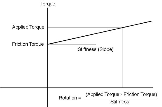
When the applied torque is less than friction torque, there is no rotation. When the applied torque exceeds friction torque, the rotation is calculated as shown above. When rotation limit is reached, there is no further rotation irrespective of the applied torque. See discussion for Kbe under Ball joint for additional information.
Weight
This is the total weight of the Hinge joint assembly. Weight is to be input in lbf or kgf and NOT in mass units. Whenever mass is required for a calculation as in the case of forming Mass matrix for dynamic analysis, or in calculating inertia force as (mass x acceleration) for static seismic analysis, CAEPIPE internally computes the mass to be equal to (weight / g-value).
Axis direction
The hinge axis is specified by the “Axis direction.” See “Direction,” for more information on specifying a direction using X comp, Y comp and Z comp.
Example
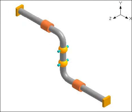
Assume that we had the model shown below (with an exaggerated deflection) containing 6” piping with a pair of Hinge joints. Each Hinge joint has the following data: rotational stiffness of 66 in.-lb./degree, and weight of 35 lb.
The following steps describe the modeling procedure (with auto node incrementing, you do not have to type in the node numbers below):
u The first node 10 is already defined as an anchor. Press Enter to move to the next row.
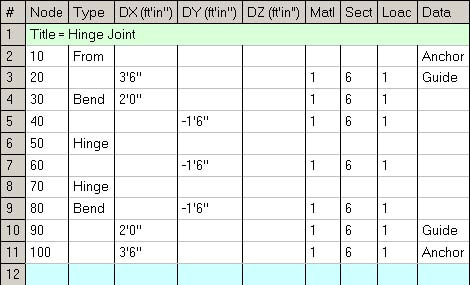
u Type 20 for Node, 3’6” for DX, enter material, section and load names, Guide for Data. Press Enter to move to the next row.
u Input bend at node 30: Type 30 for Node, press Tab to move to the Type field. Type “b” and Tab to next column to enter a bend, 2’ for DX, press Enter to move to the next row.
u Type 40 for Node, enter –1’6” for DY (as the offset from node 30 to node 40), press Enter to complete the bend and move to next row.
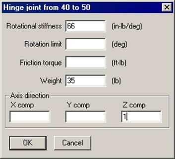
Enter 66 (in.-lb/deg.) for Rotational stiffness, 35 (lbf) for Weight, 1.0 for Z comp (axis direction), press Enter or click on OK to close the dialog. This completes the hinge input. Since there cannot be any offsets (DX, DY, DZ) for the hinge node from the previous node, the cursor automatically moves to the next row.
u Type 60 for Node, enter –1’6” for DY (as the offset from node 50 to node 60), press Enter to move to next row.
u Type 70 for Node. Type “h” in the Type column. This shows the hinge dialog. Enter the hinge data as before and click on OK to move to the next row.
u Input bend at node 80: type 80 for Node, press Tab to move to Type field, type “b” for Type and Tab to next column to enter a bend. Type –1’6” for DY (offset from node 70 to bend node 80), press Enter.
u Complete the model through nodes 90 and 100 similar to steps 1 and 2 above.
The Layout window is shown below:
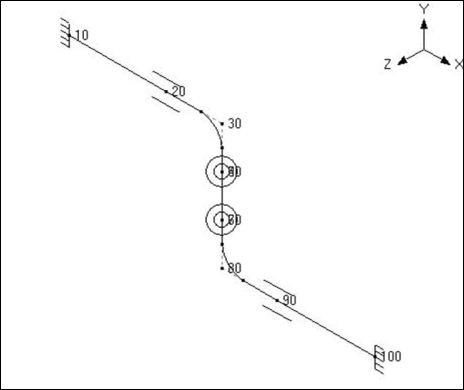
The rendered graphics is shown below:
See under Expansion Joints for more examples.