Jacketed Piping
Jacketed piping is used when the primary state of the pipe contents (fuel, chemicals such as resins, etc.) needs to be maintained at a specific temperature during transport. An outer (jacket) pipe surrounds the inner (core) pipe that contains the operating fluid or the chemical. The jacket provides external heating or cooling as required along the length of the core pipe.
The terminology used here is as follows:
· Jacketed piping refers to the entire assembly, i.e., a core pipe with a jacket on the outside.
· Jacket pipe refers only to the outside pipe.
· Core pipe refers only to the inside pipe that contains the operating fluid.
· Jacket End Cap - At nodes where the jacket terminates, the ends of the core and jacket pipes are rigidly connected using the "Jacket End Cap".
· Spider – Connects the core pipe to the jacket pipe.
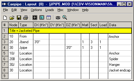
In CAEPIPE, jacketed piping need only be modeled once, not twice (as in some other pipe stress software programs). CAEPIPE models the outer jacket pipe along with the inner core pipe once on the Layout window. Each row defines a jacketed piping element. The jacket and the core pipes may have different materials, sections and (P, T) loads.
General guidelines for modeling the Jacketed Piping
· When a jacketed pipe (Jpipe) is modeled between two nodes—say, 10 and 20—the software automatically creates internal jacket nodes 10J and 20J. These jacket nodes can be referenced on the layout screen to define data such as supports or loads on the jacket.
o For jacketed bends, CAEPIPE similarly generates additional internal nodes:
o The core pipe bend uses nodes A and B at the near and far ends of the bend.
The jacket bend uses nodes C and D at its corresponding ends.
o For example, defining a jacketed bend from node 10 to the tangent intersection node 20 results in:
o 20A and 20B: end nodes for the core bend.
o 20C and 20D: end nodes for the jacket bend.
Note: Nodes 20A/20C and 20B/20D are coincident only when the core and jacket pipes have identical bend radii. The C and D nodes can also be used to apply data such as forces or supports on the jacket side of the bend.
· The bend radius of the core pipe is typically the same as that of the jacket pipe, as the two bends are usually concentric. To ensure this, you can assign equal bend radii to both the core and jacket pipes by editing the Jbend element - simply double-click the Jbend using the left mouse button to open its properties.
· At nodes where the jacket terminates, the ends of the core and jacket pipes must be rigidly connected using the "Jacket End Cap" data type available in CAEPIPE. When a Jacket End Cap is specified at a node, CAEPIPE treats the core and jacket as tied together at that location. As a result, in the Operating Displacement output, you’ll observe that all three translational and three rotational displacements are identical for both the core and jacket nodes at that point.
· The “Spider” data type must be used at locations where the core and jacket are physically connected in a jacketed piping assembly. To model these connections, you may need to divide the piping into smaller elements and insert spiders at the appropriate points that reflect the actual physical configuration.
When a Spider is specified at a node, CAEPIPE treats the core and jacket as laterally connected at that location. Accordingly, in the Operating Displacement results, you will notice that the two lateral translational displacements of the core and jacket are identical, while the axial and three rotational displacements may differ.
· The internal pressure for the core pipe element and that for the corresponding jacket pipe element could be different and should be separately input. When input, then CAEPIPE will use the net pressure for the core pipe (= internal pressure for the core pipe – internal pressure for the jacket pipe) to compute pressure stress for that core pipe element.
· Similarly, the temperature for the core pipe element and that for the corresponding jacket pipe element could be different and should be separately input.
· Piping supports should generally be attached to the jacket pipe, not the core pipe. Additionally, to ensure proper load transfer, a “Spider” connection should be added at that node to tie the core and jacket together.
· At branch connections, a Branch SIF (Stress Intensification Factor) must be specified for both the core pipe and the jacket pipe.
Jacketed Pipe
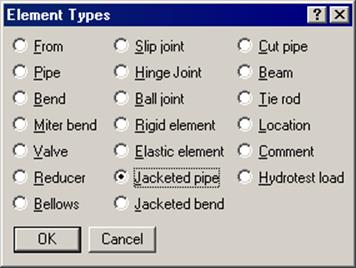
A Jacketed pipe is input by typing “JP” under Type or selecting “Jacketed pipe” from the Element Types dialog. The material, section and load specified in the Jacketed Pipe dialog apply to the jacket pipe while the ones mentioned on the layout row (next to offsets) apply to the core pipe.
The Jacketed Pipe dialog is shown.
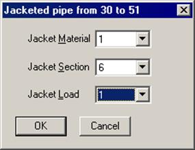
The jacket’s material, section, and load names are input here (1, 6 and 1 as shown). CAEPIPE retains the properties of a jacket pipe until changed so there is no need to retype the names of the jacket properties every time you input a jacketed pipe.
The ends of the jacket and core pipes need to be rigidly connected using the “Jacket End cap” data type (see previous topic). Also, “Spiders” need to be input at locations found in the physical assembly. You may have to break up the piping into smaller elements to insert spiders at appropriate locations. See example given later in this section.
In case you are analyzing for wind, it may be more accurate to specify a different load for the core pipe alone that does not specify the Wind load since the core pipe is not exposed to wind. Same applies to the core pipe insulation if the core pipe does not have insulation.
Internal nodes
CAEPIPE generates a “J” node for jacket pipes. For example, if you had a jacketed pipe from node 10 to 20, CAEPIPE generates 10J and a 20J as (internal) jacket nodes (that may be referenced on the layout screen).
These internally generated nodes may be used to specify data items such as a spider, jacket end cap, support (hanger, restraint), and forces on the jacket. See example later in this topic.
A Jacketed bend consists of a core bend (with a straight portion) surrounded by a jacket bend (with a straight portion of jacket pipe).
A Jacketed bend is input by typing “JB” in the Type column or by selecting “Jacketed bend” from the Element types dialog.
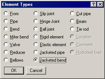
The Jacketed Bend dialog is shown.
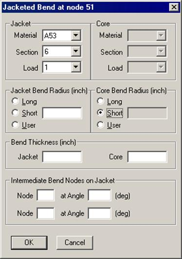
Jacket (properties)
The jacket’s material, section, and load names are input here. The properties of a jacketed pipe are retained until changed. So, there is no need to retype the names of the jacket properties every time you input a jacketed pipe.
Core (properties)
Presently these properties are disabled. You need to enter them on the layout row under Material, Section and Load.
Bend radius
Separate bend radii may be specified for the core and the jacket pipes.
Note that CAEPIPE does not check for interference between the core and the jacket arising out of differently specified bend radii.
The bend radius for the core pipe is normally the same as that of the jacket pipe, since the two bends are generally concentric. Use the Render feature in the Graphics window to check visually for interference, however.
Bend thickness
Separate bend thicknesses may be specified for the core and the jacket bends, if they are not default jacket and core section thicknesses.
Intermediate nodes
You can define additional nodes on the outside jacket of a jacketed bend for locating supports. You may also use internal nodes generated by CAEPIPE. See Internal nodes below.
Internal nodes
CAEPIPE generates “C” and “D” nodes for the Jacketed bend on the jacket at the near and far ends of the bend. The core pipe (bend) has its own “A” and “B” nodes. Example: When you define a Jacketed bend from node 20 to node 30, 30A, 30B (nodes on core bend), 30C and 30D (nodes on jacket) are generated. Nodes (30A, 30C) and (30B and 30D) are coincident only if the core and the jacket pipes have the same bend radii. See figure.
These internal nodes may be used to specify data items such as a spider, jacket end cap, supports, forces, etc.
Split a Bend/Pipe
A jacketed pipe/bend may be split by using the Split option in the Edit menu in the Layout window.
Contents Weight
The weight of the contents between the jacket and the core pipes is calculated in the following manner:
(a) Twice the insulation thickness on the core pipe is added to the outer diameter of the core pipe. (b) The external area of the core pipe is calculated by using the above diameter (a). (c) The internal area of the jacket pipe is calculated. (d) The external area of the core pipe (b) is subtracted from the internal area of the jacket pipe (c) and this result is further used to compute the weight of contents between the jacket and core pipes.
Jacketed Reducer
See modeling procedure in topic on the Reducer.
The figure below shows a Jacketed pipe with a Jacketed bend (at node 20-TIP). Observe the spider at the far end of the bend (node 20B).
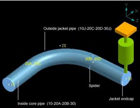
The nodes 10J, 20C, 20D, 30J, 20A and 20B are internally generated nodes. You may use them for specifying data items such as spiders, supports (hanger, restraint), forces, etc.
The pairs of nodes (10, 10J) and (30, 30J) are coincident. The nodes 20A and 20B are coincident with the nodes 20C and 20D respectively only if the core and the jacket pipes have the same bend radii.
Note that the core and jacket nodes are not connected even though they are coincident. The core and jacket pipes have to be supported and connected using supports and jacket connections (namely, spiders and jacket end caps). An anchor each at nodes 10 and 10J is specified. The hanger is at node 30J since it is attached to the jacket.
A jacket connection of the type spider at node 20B acts as an internal guide between the core pipe and the jacket pipe, that is, it prevents any radial movement but allows sliding, rotating and bending movement between core and jacket pipes.
In case forces transmitted from core pipe to jacket through spiders are required, then spiders specified on core pipe can be replaced by guides with “connected to” nodes specified as the corresponding nodes on the jacket pipe.
The end cap at node 30 connects the core and jacket pipes rigidly.
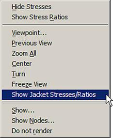
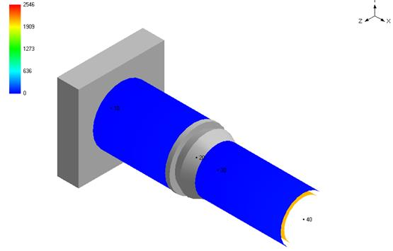
Jacketed Piping Stresses/Ratios
CAEPIPE provides an option for you to display the color-coded stress/ratio contour for jacketed piping in the graphics window context menu. The default stress contour is for the core piping. Upon selecting the command for Jacket stresses as shown below, stress contour plot for the jacket piping is displayed: