Load
Loads on a piping system can be many and varied along its routing. Different piping segments may experience different pressures and temperatures depending on process requirements, different loads (snow, wind, etc.) depending on their physical locations and carry different states of a fluid between different points in a piping system. CAEPIPE offers a flexible method to input as many loads as required for as many segments or elements as needed with the least effort.
So, Load allows you to apply a temperature and pressure, specify weight of the operating fluid and add additional weight (e.g., due to snow load) on each element (if required) or for a range of elements in the model. Also the wind load can be turned “on” or “off” for each element (if required) or for a range of elements in the model.
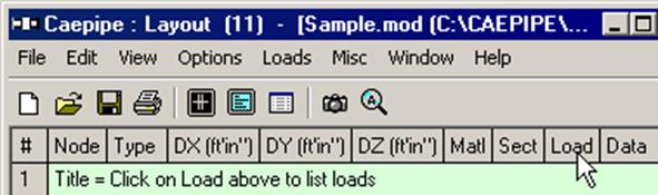
After specifying the requested information here, including a name, use it under the Load column on the Layout window to associate the load information with an element.
Each load allows up to 10 operating conditions for Temperature and Pressure depending on the “Number of Thermal Loads” specified under Options > Analysis > Temperature. This Load is not to be confused with Load cases [which are combinations of load(s)] found under the Loads menu in the Layout window. Load cases are analysis cases (Sustained case, Thermal case, Operating case, Static Seismic case, etc.) for which CAEPIPE computes a set of results.
To define a new load, click on Load in the Header row in the Layout window (or select Loads under the Misc menu, hotkey: Ctrl+Shift+L). This opens a List window that displays currently defined loads.
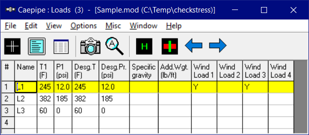
Either you can start typing the load data directly here into the fields or double click on an empty row to enter data through a dialog.
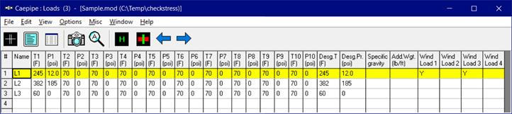
Depending on the number of thermal loads specified (under Options > Analysis > Temperature), up to 10 temperature/pressure load sets (T1/P1, T2/P2, T3/P3,…,T10/P10) can be input for each element or for a range of elements.
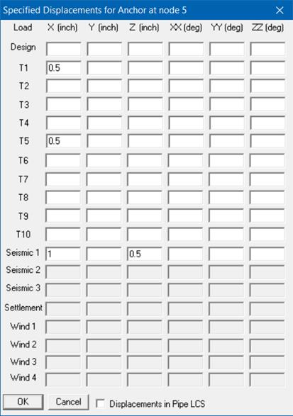
Up to 11 specified thermal displacements (including Design) can be entered for Anchor, Generic Support and Nozzle data types.
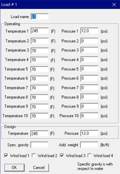
Load Name
Type an alphanumeric name (up to five characters) in this field. The name can be changed later.
Temperature s
s
Type up to 10 operating temperatures. The maximum of the 10 temperatures is used to look up the corresponding allowable stress for the material used in code evaluation.
The other quantities looked up using these temperatures are the thermal expansion coefficients (alpha) and the temperature-dependent moduli.
Make sure to select number of thermal loads equal to two, three or 10 under Options > Analysis > Temperature, when you have more than one set of temperature and pressure.
Pressure s
s
Type up to 10 operating pressures that correspond to the 10 operating temperatures above. The maximum of the 10 pressures is used to calculate the pressure stress term 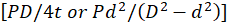 , specified under Options > Analysis > Pressure.
Specify gauge pressures for Pressures input. Negative (external) pressures may be specified, too. But, the longitudinal pressure stress term (pD/4t) will still be positive according to the piping codes. Internal pressure will expand the pipe cross-section radially outward while external (negative) pressure will contract the pipe cross-section radially inward.
Peak Pressure and Peak Temperature
Starting Version 15.00 of CAEPIPE, Design Pressure and Design Temperature have been renamed as Peak Pressure and Peak Temperature. This is done in order to avoid ambiguity in the different definitions of Design Pressure and Design Temperature as per ASME, European and other International piping codes built into CAEPIPE.
In CAEPIPE, Peak Pressure and Peak Temperature represent the maximum pressure and maximum temperature respectively that a piping component may experience at any time during its service life (including during upset/emergency/faulted condition, as referred in earlier versions of ASME Section III Nuclear Piping Codes). These peak values are not required to be coincident with each other; and they may/may not represent an operating or design load case. However, the Peak Pressure/Peak Temperature has to be respectively greater than or equal to the maximum of all operating pressures/operating temperatures input into CAEPIPE. In case the maximum of all operating temperatures is a negative temperature, then peak temperature may be input as Reference Temperature (Tref) in CAEPIPE.
These inputs are used only to compute the lowest ‘Allowable Pressure’ using the equation given in the piping code selected for analysis. For example, when ASME B31.1 (2024) is selected, CAEPIPE calculates the allowable pressure for straight pipes using Eq. (9) of para. 104.1.2:
where
Pa= allowable pressure
SE = allowable stress for the material inclusive of weld joint efficiency factor E (or casting quality factor F) at the Peak Temperature (i.e., at Tpeak input into CAEPIPE). The values of SE and SF are given in Mandatory Appendix A of ASME B31.1 (2024) Code. SE or SF is input by the user in the material properties’ dialog.
ta= available thickness = tn × (1 - mill tolerance/100) - corrosion allowance
(mill tolerance and corrosion allowance are input in Section properties’ dialog)
tn= nominal pipe thickness, input by the user in Section properties’ dialog
Do= outside diameter of pipe, input by the user in Section properties’ dialog
I = 1.0 for straight pipes
Y = coefficient as per Table 104.1.2-1 of ASME B31.1 (2024) code.
W = weld strength reduction factor as per Table 102.4.7-1 of ASME B31.1 (2024) code.
From the above equation, it is observed that the allowable pressure would be the lowest when the allowable stress term (SE) used in the numerator is at its minimum, which would happen at the highest temperature that the component may experience during its life span. Therefore, using Peak Temperature as defined above ensures the lowest allowable pressure.
Allowable pressure calculations for all piping codes are detailed in the CAEPIPE Code Compliance Manual.
The lowest allowable pressure thus calculated by CAEPIPE is then compared with the Peak Pressure input by the user and reported in the Code Compliance results. To satisfy pressure qualification requirements, the Peak Pressure must be less than or equal to the computed lowest Allowable Pressure.
When the Peak Load Case (W + PkP + PkT) is enabled via Layout Window > Loads > Load Cases, CAEPIPE also calculates forces and moments, displacements, and element forces associated with peak pressure and peak temperature effects.
Note:
The Peak pressure input is also used in computing the Occasional Stresses starting Version 15.00, irrespective of whether the Peak Load Case (W + PkP + PkT) is turned ON or OFF.
Specific Gravity
Specific gravity is the ratio of the density of a fluid to the density of a reference substance (in this case, water). Enter the specific gravity of the operating fluid inside the pipe. This input is used to calculate the weight of the operating fluid, which is added to the weight of the pipe. Specific gravity is with respect to water.
Additional weight
The value you enter here is taken as weight per unit length of the element and this total additional weight is added to the weight of the pipe. (Total additional weight = Length of element x Additional weight per unit length). Additional Weight is to be input in lbf/ft or kgf/m.
Whenever mass is required for a calculation as in the case of forming Mass matrix for dynamic analysis, or in calculating inertia force as (mass x acceleration) for static seismic analysis, CAEPIPE internally computes the mass to be equal to (weight / g-value).
For example, Additional weight could be used to apply the weight of snow on the pipe.
Wind load 1/2/3/4
Type Y(es) or N(o) to apply or not apply the wind loads for this element. When you press Y(es), the wind load (entered as a separate load under Loads menu) is applied to this element.
For example, this is useful when you have a part of a piping system exposed to wind with the remaining part inside a building. In such a case, you should define two Loads, all data the same except that one has Wind load and the other does not. The Load with the wind load is applied to those elements that are affected by wind.