Lug Evaluation
Lugs (integral attachments) are forged attachments or attachments welded on the pressure-loaded wall of a straight pipe which transfer piping loadings to the steel framework or concrete.
Loads on attachments cause local stresses in the pipe wall. Equations to determine these pipe stresses at lug attachments are given in different codes. These local stresses are then added to the piping system stresses at the attachments. The combined stresses thus obtained are checked for compliance with the appropriate equations given in those codes.
The Lug Evaluation module implemented in CAEPIPE computes local pipe stresses as per the following codes for Rectangular and Hollow Circular cross sectional attachments.
1. ASME Section III, Division 1 (2010) – Appendix Y (NC Piping – Class 2)
2. ASME Section III, Division 1 (2010) – Appendix Y (ND Piping – Class 3)
3. EN 13480-3 (2017), Section 11
The details on the implementation of this module are provided in the Section titled “Lug Evaluation” of the CAEPIPE Code Compliance Manual.
The Lug Evaluation module assumes that the flexibility analysis of that piping system with CAEPIPE has already been performed, which will have produced a stress report as well as the forces and moments at the location where the lug is attached to the piping.
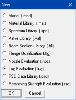
Note that this module is separate from a piping stress model file and can be accessed from File Menu > Open/New command.
Double-clicking anywhere in the previous screen (or Edit menu > Edit (Ctrl+E)) opens a dialog with input fields you can edit. You will need to enter the data in this dialog. The different parameters required to be input are explained in detail in the Section titled “Lug Evaluation” of the Code Compliance manual.
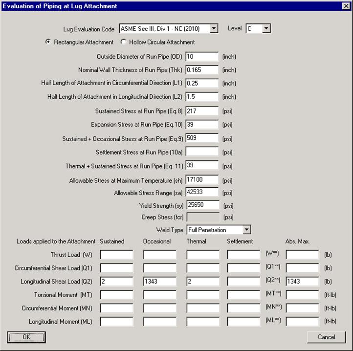
Once the required data are input, save the file (Lug evaluation will have a .lug extension). Now, select File menu > Analyze to calculate stresses and perform code evaluation, which will be shown right below the input information.
Lug Evaluation Module Menus
File Menu
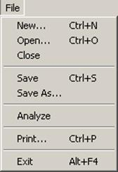
Analyze
Analyze command calculates pipe stresses at the attachment and compares them to stress allowable specified by the selected code.
Print
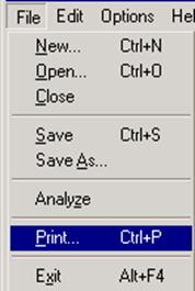
You can print a Report by using the Print command. You can also preview the report by clicking the Preview button on the print dialog.
Edit Menu
Edit
You can edit the data by clicking the Edit command.
Options Menu
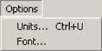
Units
See Units in the Layout Window Options Menu section of the CAEPIPE User’s Manual.
Font
See Font in the Layout Window Options Menu section of the CAEPIPE User’s Manual.
Sample Problem
-----------------------------------------------------------------------------------
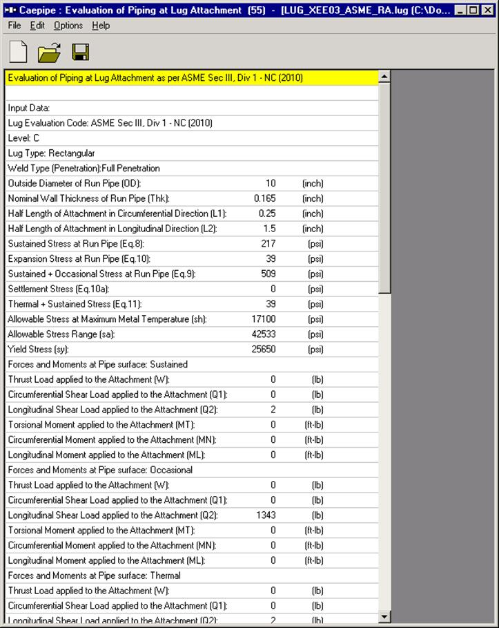
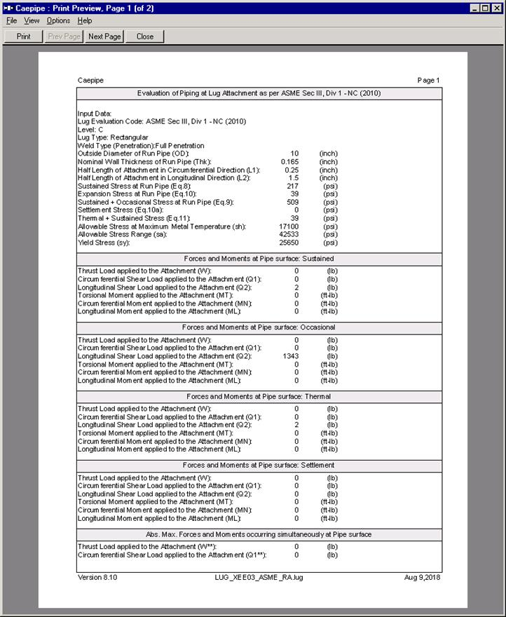
Evaluation of Piping at Lug Attachment as per ASME Sec III, Div 1 - NC (2010)
-----------------------------------------------------------------------------------
Input Data:
Lug Evaluation Code: ASME Sec III, Div 1 - NC (2010)
Level: C
Lug Type: Rectangular
Weld Type (Penetration):Full Penetration
Outside Diameter of Run Pipe (OD): 10 (inch)
Nominal Wall Thickness of Run Pipe (Thk): 0.165 (inch)
Half Length of Attachment in Circumferential Direction (L1): 0.25 (inch)
Half Length of Attachment in Longitudinal Direction (L2): 1.5 (inch)
Sustained Stress at Run Pipe (Eq.8): 217 (psi)
Expansion Stress at Run Pipe (Eq.10): 39 (psi)
Sustained + Occasional Stress at Run Pipe (Eq.9): 509 (psi)
Settlement Stress (Eq.10a): 0 (psi)
Thermal + Sustained Stress (Eq.11): 39 (psi)
Allowable Stress at Maximum Metal Temperature (sh): 17100 (psi)
Allowable Stress Range (sa): 42533 (psi)
Yield Stress (sy): 25650 (psi)
-----------------------------------------------------------------------------------
Forces and Moments at Pipe surface: Sustained
-----------------------------------------------------------------------------------
Thrust Load applied to the Attachment (W): 0 (lb)
Circumferential Shear Load applied to the Attachment (Q1): 0 (lb)
Longitudinal Shear Load applied to the Attachment (Q2): 2 (lb)
Torsional Moment applied to the Attachment (MT): 0 (ft-lb)
Circumferential Moment applied to the Attachment (MN): 0 (ft-lb)
Longitudinal Moment applied to the Attachment (ML): 0 (ft-lb)
-----------------------------------------------------------------------------------
Forces and Moments at Pipe surface: Occasional
-----------------------------------------------------------------------------------
Thrust Load applied to the Attachment (W): 0 (lb)
Circumferential Shear Load applied to the Attachment (Q1): 0 (lb)
Longitudinal Shear Load applied to the Attachment (Q2): 1343 (lb)
Torsional Moment applied to the Attachment (MT): 0 (ft-lb)
Circumferential Moment applied to the Attachment (MN): 0 (ft-lb)
Longitudinal Moment applied to the Attachment (ML): 0 (ft-lb)
-----------------------------------------------------------------------------------
Forces and Moments at Pipe surface: Thermal
-----------------------------------------------------------------------------------
Thrust Load applied to the Attachment (W): 0 (lb)
Circumferential Shear Load applied to the Attachment (Q1): 0 (lb)
Longitudinal Shear Load applied to the Attachment (Q2): 2 (lb)
Torsional Moment applied to the Attachment (MT): 0 (ft-lb)
Circumferential Moment applied to the Attachment (MN): 0 (ft-lb)
Longitudinal Moment applied to the Attachment (ML): 0 (ft-lb)
-----------------------------------------------------------------------------------
Forces and Moments at Pipe surface: Settlement
-----------------------------------------------------------------------------------
Thrust Load applied to the Attachment (W): 0 (lb)
Circumferential Shear Load applied to the Attachment (Q1): 0 (lb)
Longitudinal Shear Load applied to the Attachment (Q2): 0 (lb)
Torsional Moment applied to the Attachment (MT): 0 (ft-lb)
Circumferential Moment applied to the Attachment (MN): 0 (ft-lb)
Longitudinal Moment applied to the Attachment (ML): 0 (ft-lb)
-----------------------------------------------------------------------------------
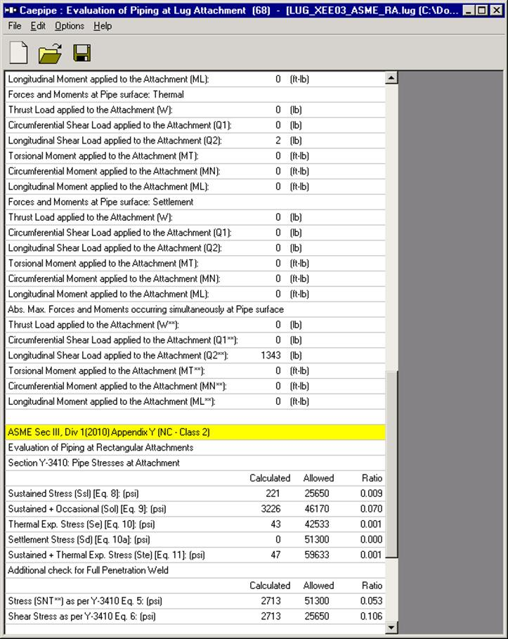
Abs. Max. Forces and Moments occurring simultaneously at Pipe surface
-----------------------------------------------------------------------------------
Thrust Load applied to the Attachment (W**): 0 (lb)
Circumferential Shear Load applied to the Attachment (Q1**): 0 (lb)
Longitudinal Shear Load applied to the Attachment (Q2**): 1343 (lb)
Torsional Moment applied to the Attachment (MT**): 0 (ft-lb)
Circumferential Moment applied to the Attachment (MN**): 0 (ft-lb)
Longitudinal Moment applied to the Attachment (ML**): 0 (ft-lb)
-----------------------------------------------------------------------------------
ASME Sec III, Div 1(2010) Appendix Y (NC - Class 2)
-----------------------------------------------------------------------------------
Evaluation of Piping at Rectangular Attachments
-----------------------------------------------------------------------------------
Section Y-3410: Pipe Stresses at Attachment
-----------------------------------------------------------------------------------
Calculated Allowed Ratio
(psi) (psi)
Sustained Stress (Ssl) [Eq. 8]: (psi) 221 25650 0.009
Sustained + Occasional (Sol) [Eq. 9]: (psi) 3226 46170 0.070
Thermal Exp. Stress (Se) [Eq. 10]: (psi) 43 42533 0.001
Settlement Stress (Sd) [Eq. 10a]: (psi) 0 51300 0.000
Sustained + Thermal Exp. Stress (Ste) [Eq. 11]: (psi) 47 59633 0.001
-----------------------------------------------------------------------------------
Additional check for Full Penetration Weld
-----------------------------------------------------------------------------------
Calculated Allowed Ratio
(psi) (psi)
Stress (SNT**) as per Y-3410 Eq. 5: (psi) 2713 51300 0.053
Shear Stress as per Y-3410 Eq. 6: (psi) 2713 25650 0.106