Nozzle
Nozzles are integral attachments of vessels (such as pressure vessels, storage tanks etc.) which connect with external piping. Nozzles transmit the shell (vessel) flexibility to the piping system and hence are generally included in piping stress analysis.
Three types of nozzles can be modeled in CAEPIPE, namely (i) a nozzle attached to a cylindrical vessel relatively far from the ends of the cylinder, (ii) a nozzle attached to a spherical vessel or torispherical head and (iii) a nozzle attached to a cylindrical shell with a flat bottom and close to the flat-bottom. CAEPIPE calculates the nozzle stiffnesses (local flexibility components) according to WRC 297, PD 5500 and API 650 guidelines. See Section titled “Nozzle Stiffnesses” in CAEPIPE Code Compliance Manual for further details.
Note:
Pressure Thrust (End-cap Force) of Pressure P x Inner Area (A) of pipe is not included in the Support Loads for Nozzles displayed by CAEPIPE at this time. Since CAEPIPE’s results for numerous problems compare well with the results from other third-party software, it confirms that the other stress programs are also not including the Pressure Thrust (End-cap Force) of pipe in the Nozzle Loads at this time. Refer to the Verification Manual supplied with CAEPIPE for comparison of results with other stress programs.
If you wish to include the effect of Pressure Thrust (End-cap force) due to internal pressure in your piping on the Nozzle loads, then you will have to compute the same manually (= P x A) and input it as an external force at the Nozzle Nodes using the Force data type available with CAEPIPE. Please choose the option “Add to W+P” in the Force data type dialog. By doing so, the End-cap force (= P x A) will be included in all relevant load cases and combinations of CAEPIPE. Of course, when the “None” code is selected under Options > Analysis > Code, this End-cap force is included in the only case of “Static”.
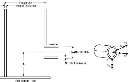
Nozzle attached to a cylindrical vessel
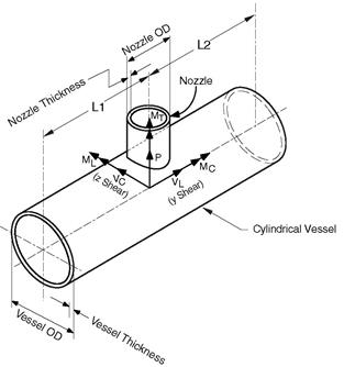
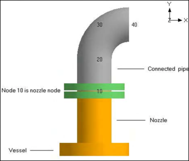
The coordinate system is as shown in the figure. The six components of the forces and moments at the nozzle-vessel interface are:
P = Radial load MC = Circumferential moment
VC = Circumferential load MT = Torsional moment
VL = Longitudinal load ML = Longitudinal moment
Of the six components of shell stiffnesses, only three stiffnesses, axial (Kx), circumferential (Kyy), and longitudinal (Kzz), are computed. The remaining three are assumed to be rigid.
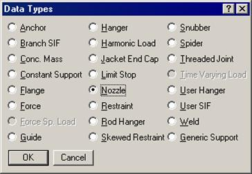
A nozzle is input by typing “n” in the Data column or selecting “Nozzle” from the Data Types dialog.
The Nozzle dialog is shown. Note that the Displacements button is disabled. It is only enabled after the nozzle is input (i.e., existing nozzle).
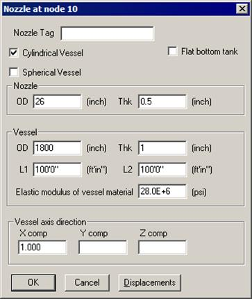
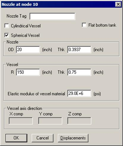
Nozzle
OD: Outside diameter of the nozzle.
Thk: Thickness of the nozzle.
Vessel
Thk: Thickness of the vessel.
L1, L2: Distances from the nozzle to the nearest stiffening ring, tube sheet or the vessel end.
Vessel axis direction
The orientation of the vessel axis in terms of its global X, Y and Z components are entered here. See example under “Specifying a Direction.”
Nozzle to Spherical / Torispherical Shell
For a nozzle attached to a spherical shell or a torispherical head, check the Spherical Vessel checkbox and enter the required details.
Nozzle attached to Flat-Bottom Tanks
For a nozzle on a flat-bottom tank and close to the flat-bottom, check the Flat-bottom tank checkbox.
A slightly modified Nozzle dialog is displayed.
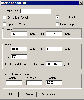
All the input fields are the same as before except:
L
L is the distance from the flat-bottom to the nozzle centerline.
Reinforcing pad
If the nozzle is reinforced, check this box.
Stiffness Calculation
Here again, only three shell stiffnesses, axial translational (i.e., axial to the pipe, the same as radial to the shell), circumferential bending and longitudinal bending are computed according to API 650 guidelines. See section titled “Nozzle Stiffnesses” in CAEPIPE Code Compliance Manual for the procedure. The remaining three shell stiffnesses are assumed to be rigid.
The flat-bottom tank nozzles are subject to the following limitations (API 650):
Limitations
u Nozzle OD/Vessel OD ratio must be between 0.005 and 0.04.
u L/Nozzle OD ratio must be between 1.0 and 1.5. See graphs in section titled “Nozzle Stiffnesses” in CAEPIPE Code Compliance Manual, Figures D-3 through D-14.
After a nozzle is input in a stress model, Displacements (translations and/or rotations) in the global X, Y and Z directions may be specified for that nozzle (for thermal, settlement and seismic cases). Click on the Displacements button. You will see a dialog similar to one shown below. Displacement fields will be enabled or disabled automatically depending upon the load cases defined. Type in specified displacements for the applicable load cases and press Enter.
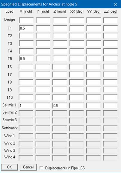
There are three types of displacements which can be specified:
1. Thermal (up to 10 displacements can be specified, one for each of the thermal loads T1 through T10). Applied only to the Expansion and Operating load cases.
2. Seismic displacements (Seismic 1, 2 and 3) are available for all codes. Solved as a separate internal load case, the results of which are added absolutely to the corresponding static seismic load cases. For response spectrum analysis, only results from Seismic 1 displacements are added absolutely to the response spectrum load.
3. Wind displacements (up to 4 sets can be specified, one each for each of the Wind loads Wind 1 through Wind 4). Applied to the corresponding Wind load cases.
4. For Piping Code = NONE, Specified Displacement results for Seismic 1 and Wind 1 load cases are “Algebraically” added to the results from all other load cases.
Check “Displacements in LCS” if you want to enter Nozzle movements in the local coordinate system. These local movements are transformed into the global coordinate system and displayed in results.
Settlement
For certain piping codes (ASME B31.1, ASME Section III Class 2, RCC-M and EN 13480), a settlement, which is a single non-repeated movement (e.g., due to settlement of foundation), may be specified. This is applied to the Settlement load case. For those codes which do not have a separate provision for settlement (like B31.3), specify the settlement as a thermal displacement (a conservative approach) for one of the temperature load and define that temperature as equal to reference temperature.
For EN13941-1, specified displacements input as Settlement are included in Sustained load case.
Example 1: Nozzle on a cylindrical vessel
Assume the following data:
Vessel Radius = 900 in.
Vessel Thickness = 1.0 in.
Nozzle OD = 26 in.
Nozzle Thickness = 0.5 in.
L1 = L2 = 1200 in.
Elastic modulus for vessel material = 28×106psi.
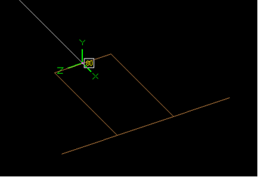
The first node (10) is already defined as an anchor. To replace the anchor by a nozzle, right click on the Anchor in the Data column, then select Delete Anchor. Then type “n” in the Data column to input the nozzle. The Nozzle dialog will be shown. Input the nozzle data in the dialog. The Layout window looks like the following:
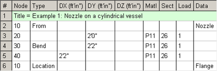
The graphics is shown next.
Nozzle Stiffnesses
The three local shell stiffnesses computed can be viewed using the List command (Ctrl+L in the Layout window) and selecting Nozzle Stiffnesses. The following window is displayed.
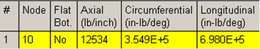
The nozzle/vessel data may be edited here (double click to edit).
Example 2: Nozzle on a spherical vessel
Assume the following data:
Vessel OD = 1800 in.
Vessel Thickness = 1.0 in.
Nozzle OD = 26 in.
Nozzle Thickness = 0.5 in.
Elastic modulus for vessel material = 28×106psi.
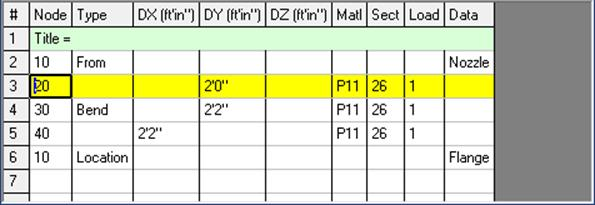
The first node (10) is already defined as an anchor. To replace the anchor by a nozzle, right click on the Anchor in the Data column, then select Delete Anchor. Then type “n” in the Data column to input the nozzle. The Nozzle dialog will be shown. Input the nozzle data in the dialog. The Layout window looks like the following:
The graphics is shown next.
Nozzle Stiffnesses
The three local shell stiffnesses computed can be viewed using the List command (Ctrl+L in the Layout window) and selecting Nozzle Stiffnesses. The following window is displayed.
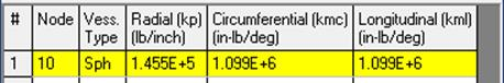
The nozzle/vessel data may be edited here (double click to edit).
Example 3: Nozzle on a flat-bottom storage tank
Assume the following data:
Vessel OD = 1800 in.
Vessel Thickness = 1.0 in.
Nozzle OD = 26 in.
Nozzle Thickness = 0.5 in.
L = 36 in.
Elastic modulus of the vessel material = 28×106psi.
No reinforcing pad on the vessel.
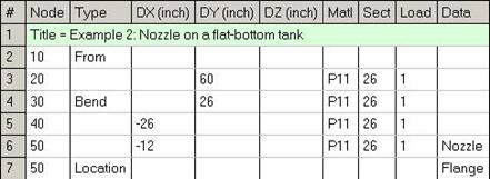
Create the piping till the nozzle node. At the nozzle node, enter a Nozzle by typing “n”, check the Flat-bottom tank checkbox and provide the required data.
The Layout window looks like the following.
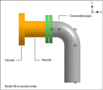
The graphics is shown next.
The three nozzle stiffnesses computed can be viewed as before by using the List command (Ctrl+L) and selecting Nozzle Stiffnesses.
1. List (Ctrl+L) > Nozzles > View menu > Show LCS, -OR-
2. List (Ctrl+L) > Nozzles > Mouse Right Click on the listed Nozzle > Show LCS, -OR-
3. Results window > Support Loads > Other Support Loads > Nozzles > View menu > Show LCS, -OR-
4. Results window > Support Loads > Other Support Loads > Nozzles > Mouse Right Click > Show LCS.