Pump
Pumps, compressors, turbines, air cooled heat exchanger and fired heaters in CAEPIPE, referred to as equipment, are each governed by an industry publication - API (American Petroleum Institute) publishes an API 610 and API 676 for pumps, ANSI (American National Standards Institute) publishes an ANSI/HI 9.6.2 for Rotodynamic Pumps, API 617 for compressors and NEMA (National Electrical Manufacturers Association) publishes the NEMA SM-23 for turbines, API 661 for air cooled heat exchangers and API 560 for fired heaters. These publications provide guidelines for evaluating nozzles connected to equipment among other technical information including the items relevant to piping stress analysis – criteria for piping design and a table of allowable loads.
Modeling the equipment is straightforward since it is assumed rigid (relative to connected piping) and modeled only through its end points (connection nozzles).
1. In your model, anchor all the nozzles (on the equipment) that need to be included in the analysis.
2. Specify these anchored nodes during the respective equipment definition through Misc. menu > Pumps/Compressors/Turbines/Air Cooled Heat Exchangers/Fired Heaters in the Layout window.
CAEPIPE does not require you to model all of the nozzles nor their connected piping. For example, you may model simply one inlet nozzle of a pump with its piping. Or, you may model one pump with both nozzles (with no connected piping) and impose external forces on them (if you have that data). Further, there is no need to connect the two anchors of the equipment with a rigid massless element like required in some archaic methods. A flange and an anchor may coexist.
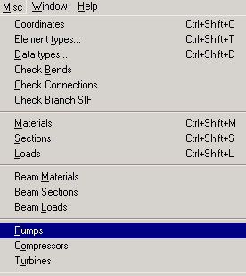
A pump is input by selecting “Pumps” from the Misc menu in the Layout or List window. CAEPIPE produces API 610 pump compliance report after analysis for 2 types of pumps, namely Horizontal and Vertical inline. Also, CAEPIPE generates ANSI /HI 9.6.2 compliance report for four types of Rotodynamic pumps: Horizontal or Vertical inline or Axial split case or Vertical turbine short set pumps. See Section titled “Equipment Qualification” from the Code Compliance Manual for related information.
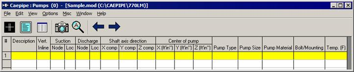
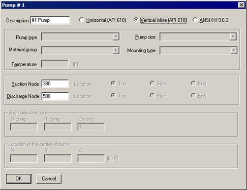
Once you see the Pump List window, double click on an empty row for the Pump dialog and enter the required information.
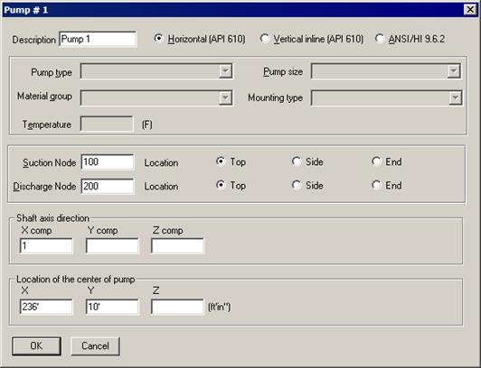
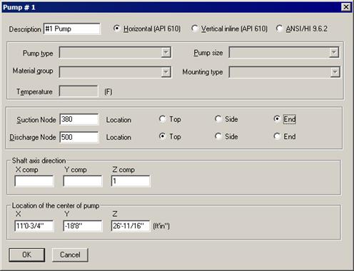
Type a short description to identify the pump in Description. You must designate the pump nozzles as anchors, and the shaft axis must be in the horizontal plane. The nozzle locations (top, side or end) should be specified for suction and discharge nodes.
See section on specifying a Direction for information on X comp/Y comp/Z comp.
For horizontal pumps, you must enter coordinates for the center of the pump with respect to global origin. For pumps with two support pedestals, API 610 defines the center by the “intersection of the pump shaft centerline and a vertical plane passing through the center of the two support pedestals.” For pumps with four support pedestals, the center is defined by the “intersection of the pump shaft centerline and a vertical plane passing midway between the four pedestals.” See Section titled “Equipment Qualification” of the Code Compliance Manual for illustrative figures.
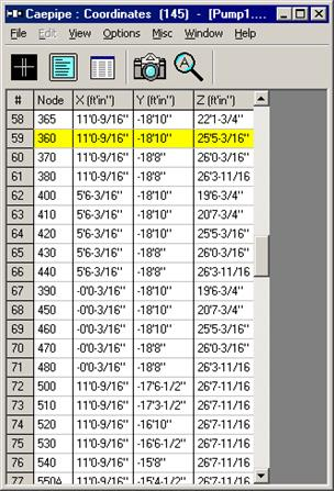
You might find it helpful to first model the nozzles as anchors. In some situations, you might not have the discharge or suction side piping. In that case, here is how you can fix the location of the other side. Look up the coordinates of the nozzle (anchor) you have already modeled.
Then, use the coordinates command (menu Misc > Coordinates) to note the (X, Y, Z) coordinates of this pump nozzle node number. Using its coordinates, you can now arrive at the required coordinates of the other side’s nozzle and the center of the pump.
Example – API 610 Pump Compliance
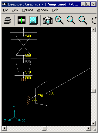
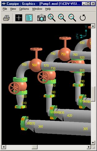
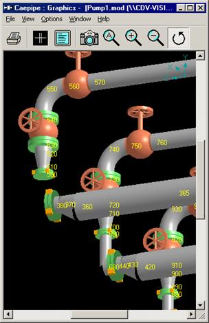
In the above image, suction side piping ends at node 380. Discharge piping starts at node 500. In the Pump definition dialog (shown next), you can see that the center of the pump is just behind the suction nozzle (node 380) coordinates. The reducer between nodes 370 and 380 is a vertically offset eccentric reducer; hence the graphics at the reducer shows a break.
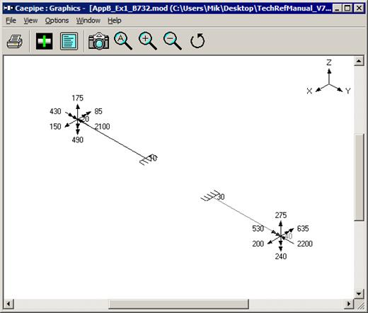
A simpler example is when you do have piping on both sides of the pump. Consider the network below consisting of two pipe segments connected by a pump.
(suction side) 10-20-30-…-90-100→PUMP←200-210-…-280-290-300 (discharge side)
The suction side of the pump ends at node 100. The discharge side begins at node 200. Make nodes 100 and 200 as anchors so that equipment loads can be calculated. A similar method applies to turbines and compressors too.
A different dialog is shown for vertical inline pumps. Only Description, Suction and Discharge nodes are required.
Dialog box for Positive Displacement Pump is shown below. Only Description, Suction and Discharge nodes are required.
API 610 Report
Upon analysis, you will see CAEPIPE produce API 610 reports under “Equipment Qualification” in Results.
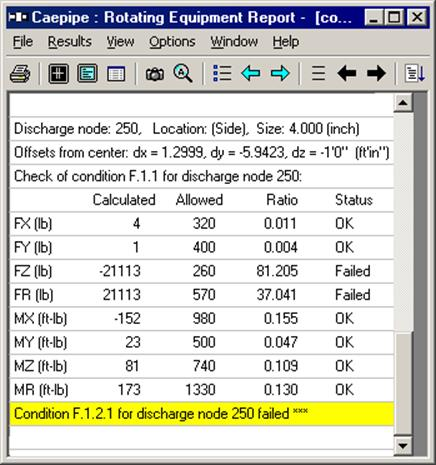
In addition to the input details, for a specific load case, the calculated forces and moments (on the nozzle and those at the center of the pump), API allowable, ratios (of calculated to allowable) and status for all of them are reported.
When you see “Failed” entries in this report, you will need to examine the cause of the high force or moment for that line item. Generally, the high numbers come from the expansion load but may well come from the weight load. You must reduce these excessive forces and moments by making the system or intersections more flexible before this pump can become compliant.
Note: If you have input multiple temperatures, corresponding reports for additional operating load cases are shown. Use the black right arrow key to see them.
Example – ANSI/HI 9.6.2 Pump Compliance
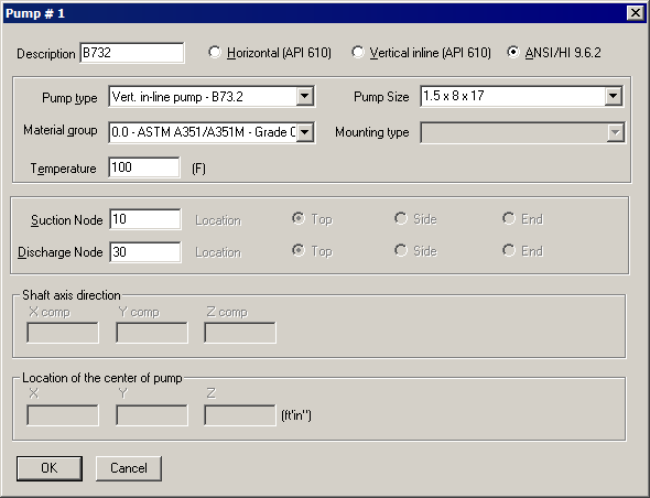
In the above image, suction side piping ends at node 10. Discharge piping starts at node 30. Pump size is 1.5 x 8 17 with Material Group ASTM A351/A351M – Grade CF8M. The temperature of the pump is set to 1000 F.
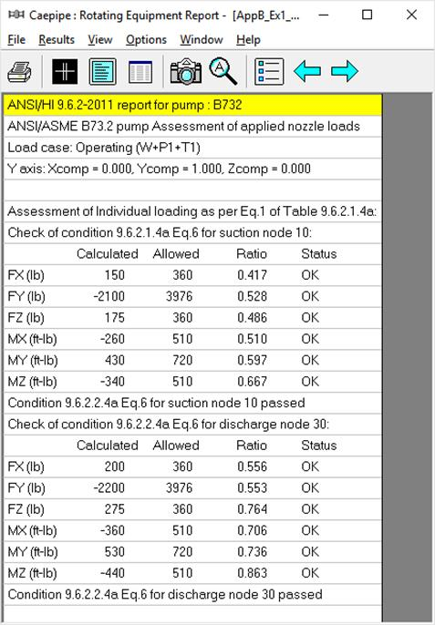
ANSI/HI 9.6.2 Report
Upon analysis, you will see CAEPIPE produce ANSI/HI 9.6.2 reports under “Equipment Qualification” in Results.
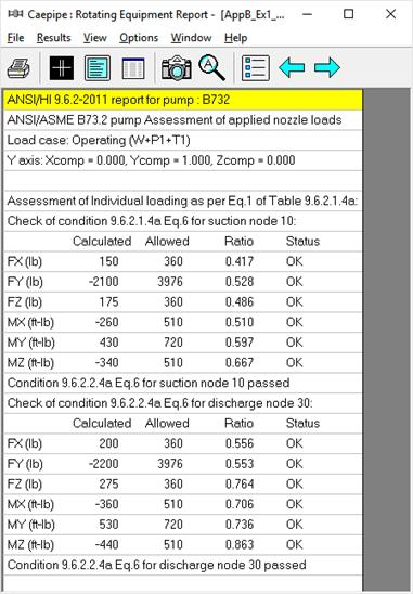
In addition to the input details, for a specific load case, the calculated forces and moments, ANSI/HI 9.6.2 allowable, ratios (of calculated to allowable) and status for all of them are reported.
When you see “Failed” entries in this report, you will need to examine the cause of the high force or moment for that line item. Generally, the high numbers come from the expansion load but may well come from the weight load. You must reduce these excessive forces and moments by making the system or intersections more flexible before this pump can become compliant.
Note: If you have input multiple temperatures, corresponding reports for additional operating load cases are shown. Use the black right arrow key to see them.