Remaining Strength Evaluation – ASME B31G (2023)
Remaining Strength of Corroded Pipeline is evaluated as per ASME 31G (2023). The details of the implementation are provided in CAEPIPE Code Compliance Manual.
The B31G Criterion and the Modified Criterion for assessing the remaining strength of corroded line pipe are based on semi-empirical mathematical expressions that involve assumptions, approximations, and generalizations designed to simplify calculation and to yield a result in accord with actual in-service performance of corroded pipelines. Specially, these mathematical expressions are founded on established principles of fracture mechanics and full-scale pressure tests of line pipe with blunt part-wall corrosion defects. The burst pressure of a line pipe with a blunt part-wall corrosion defect is controlled by:
1. Defect size and shape,
2. Flow stress of the material, and
3. Geometry correction factor.
Defect Size and Shape
Blunt part-wall defects in line pipe are idealized differently in the B31G Criterion and the Modified Criterion.
· In the B31G Criterion, blunt part-wall defects are idealized as a parabolic shape of length, L, depth, d, and cross-section equal 2/3 × L × d where depth, d, is less than or equal to 80% of the wall thickness, t, of the line pipe. Tables and equations are provided in ASME B31G (2023) for establishing corrosion limits for a range of pipe diameters, wall thicknesses, and pit depths. They also provide reference to corrosion length and depth combinations needed to determine whether a corroded region of a pipeline must be repaired, replaced, or operated at a pressure below the maximum allowable operating pressure (MAOP).
· In the 0.85dL Method, blunt part-wall defects are idealized as an arbitrary cross-section equal 0.85 × L × d where, L, is defect length and, d, is the defect depth that is less than or equal to 80% of the wall thickness, t, of the line pipe. These defect profiles are used in the 0.85dL Method to establish safe operating pressures.
· In the Exact Trapezoid method, blunt part-wall defects are idealized as various subsections of the total area of metal loss where the total area of the cross-section is calculable by summing the areas of the trapezoids formed by the discrete depth measurement points within a given length the corroded area is numerically computed using the trapezoid method.
· In the Equivalent Area method, the corroded area is determined by multiplying the average pit depth by the flaw length. Additionally, an equivalent flaw length (flaw length * average pit depth / maximum pit depth) is used in the computation of the Folias factor.
· In the Effective Area method, blunt part-wall defects are idealized as various subsections of the total area of metal loss where the total area of the cross-section is calculable by summing the areas of the trapezoids formed by the discrete depth measurement points within a given length. The detailed profile is established by obtaining several measurements of metal loss or remaining wall thickness throughout the metal loss area and projecting those measurements onto a longitudinal plane of the pipe wall that extends through the axial length of the area of metal loss. For a corroded profile defined by n measurements of depth of corrosion including the end points at nominally full wall thickness, n!/2(n − 2)! iterations are required to examine all possible combinations of local metal loss with respect to surrounding remaining material. This iterative algorithm is used to identify the minimum safe operating pressure.
Flow Stress of the Material
The B31G Criterion and the Modified Criterion assume that the burst pressure of a line pipe is attributed to a flow-stress mechanism that is controlled by the defect profile and the tensile properties (yield strength, ultimate tensile strength) of the line pipe steel. Therefore, these line pipe steels must have isotropic material properties, exhibits non-linear strain-hardening behavior, satisfies the assumed flow stress criterion, and have adequate toughness so that the failure pressure is more than that predicted by plastic collapse.
The assumed flow stress in the:
· B31G Criterion equals 1.1 times the specified minimum yield strength (SMYS) for the material (i.e., 1.1*SMYS).
· Modified Criterion equals SMYS for the material plus 10,000 psi (i.e., SMYS + 10,000 psi).
Geometry Correction Factor
Curved steel plates that contain through cracks have a reduced resistance to fracture initiation. Consequently, a crack in the wall of a pressure vessel or pipe can severely reduce its ability to resist internal pressure. Relationships that exist among fracture load, flaw shape and size, material properties, and structural geometry are called fracture criterion. This fracture criterion can be derived by the application of the theory of fracture mechanics. The failure criterion that relates a cylindrical pressure vessel or pipe to a flat plate and accounts for the curvature of the pressure vessel or pipe is called the “Folias” factor (also known as bulging factor).
A two-term “Folias” factor is used in the B31G Criterion to determine the safe maximum pressure for a corroded region with a defect length, L, less than or equal to  , where, D, is the pipe diameter and, 𝑡 is the pipe wall thickness.
Different “Folias” factors are used in the Modified Criterion depending on the length, L, of the defect. A three-term “Folias” factor is used to determine the safe maximum pressure for a corroded region with a defect length, L, equal to or less than  , and a two-term “Folias” factor is used to determine the safe maximum pressure for a corroded region with a defect length, L, greater than .
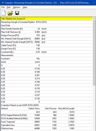
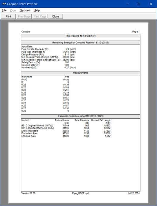
In summary, CAEPIPE determines the following values according to the original B31G criteria and four modified methods detailed above in Subsection “Defect Size and Shape”.
· The hoop stress to cause failure (Failure Stress)
· The maximum allowed operating pressure (Safe Pressure)
· The maximum allowed defective length
Note that this module is separate from a piping stress model file and can be accessed from File Menu > Open/New command.
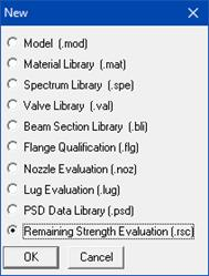
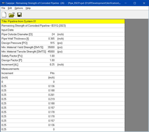
The software opens the Remaining Strength Evaluation window as shown below.
Double clicking on the window shown above will open a dialog box consisting of two set of inputs as shown below.
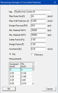
Input the required parameters and save the data. Design Factor and Minimum Material SMTS values are not used in the evaluation at this time. See the Section titled “Remaining Strength of Corroded Pipeline” in CAEPIPE Code Compliance Manual for details on implementation. To obtain the results from the evaluation as given below, select the option File > Analyze.
Module Menus
File Menu
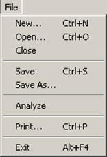
You can print a Report by using the Print command. You can also preview the report by clicking the Preview button on the print dialog.
Edit Menu
Edit
You can edit the data by clicking the Edit command.
Options Menu
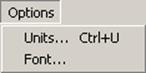
Units
See Units in the Layout Window Options Menu section of the CAEPIPE User’s Manual.
Font
See Font in the Layout Window Options Menu section of the CAEPIPE User’s Manual.