Skewed Restraint
A Skewed Restraint is a two-way support that resists translation along or rotation about any specified direction at a node. You have to use either a manufacturer-supplied stiffness or calculate it for the support you want to model.
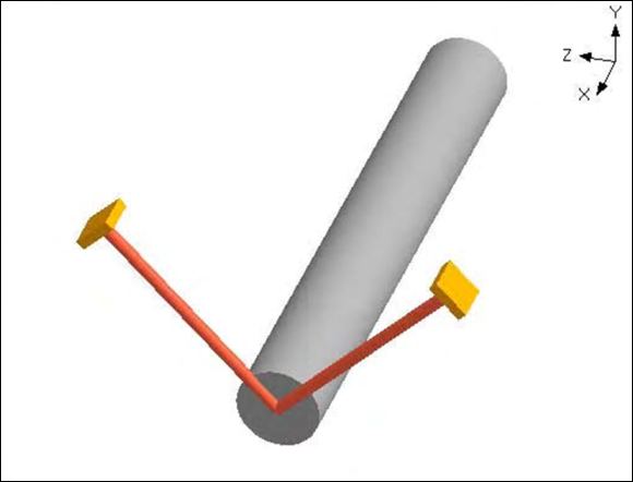
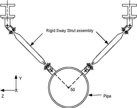
Use this restraint to model sway braces, sway struts and similar supports. You can also use this to model vertical/horizontal supports, though it is used more commonly to resist lateral forces.
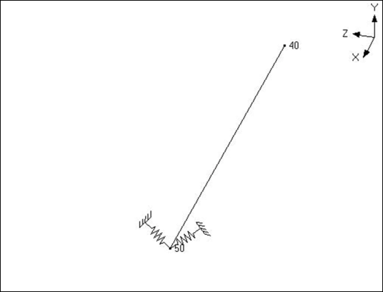
The figure below shows an application.
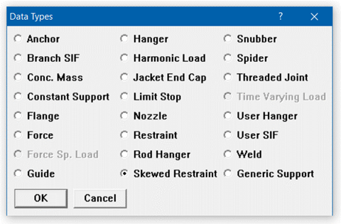
A skewed restraint is input by typing “sk” in the Data column or selecting “Skewed restraint” from the Data Types dialog.
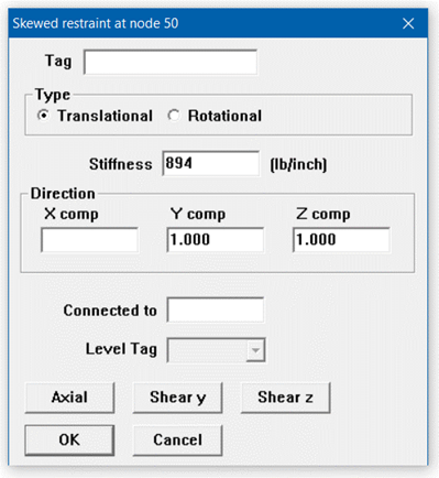
The Skewed Restraint dialog is shown.
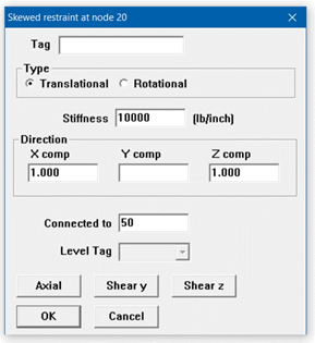
Translational: Use this type to restrain translation along the specified direction.
Rotational: Use this type to restrain rotation about the specified direction.
Stiffness
Type in the translational or rotational stiffness of the support. As an illustration, assume that you had a rod (in tension only) which you were modeling as a skewed restraint. You can calculate the stiffness (required to be input) in the following manner: Assume a 2.5 in. dia. rod 2 feet long, modulus of elasticity of rod material = 30×106 psi.
The translational (axial) stiffness is 
The rotational stiffness is 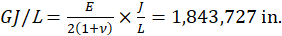 -
- where
where  is the shear
modulus,  is the Poisson’s ration and
  is polar moment of inertia.
Direction
If you have no “connected to node,” the direction in which the skewed restraint is oriented must be specified in terms of its global X, Y and Z components. See topic on specifying a Direction.
If the skewed restraint node is connected to an externally fixed point (ground), then for the Direction vector components (X comp, Y comp, Z comp), you can specify the offsets (DX, DY, DZ) from the skewed restraint node to the fixed point.
Or use one of the preset buttons to orient the skewed restraint axis:
1. Axial: To set the axis along the local-x direction (pipe axis)
2. Shear y: To set the axis in the local-y direction
3. Shear z: To set the axis in the local-z direction
If you have connected the skewed restraint node to another node, then the direction must not be input. It is calculated from the locations of the skewed restraint node and the connected node, and it is oriented from the skewed restraint node towards the connected node. In order for CAEPIPE to calculate the direction, the skewed restraint node and the connected node must not be coincident.
Connected to node
If the skewed restraint node is connected to an externally fixed point (ground), leave the “Connected to node” blank. You may connect a skewed restraint node to another node that is not coincident with the skewed restraint node. Note that during skewed restraint force calculations, the relative displacement of the skewed restraint node is calculated with respect to the connected node.
Example: Modeling a Sway Brace
Assume that we need to model two sway braces in the same arrangement as shown in the figure at the beginning of this section. The translational stiffness of the sway braces is given as 894 lb./in. As can be surmised from the figure, the orientation of the sway braces (sway struts in the figure) is at 45° from the Y- and Z-axes. We shall model the support on the right hand side first followed by the support on the left hand side.
The following steps describe the modeling procedure:
u Create node (on pipeline) where support is required. In this case, the node is 50. Position highlight on this row.
u First support (right): Type “sk” in the Data column to open the skewed restraint dialog box.
Ensure that Type is set to Translational; if not, click on the Translational radio button. Type 894 for Stiffness, type 1 for Y comp and –1 for Z comp, press Enter.
u Second support (left): type 50 for Node on an empty row, press Tab to move to next field, press “l(L)” for Location. This will open the Data types dialog.
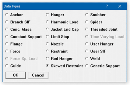
Select Skewed restraint by clicking on it to open the skewed restraint dialog. Enter the skewed restraint dialog similar to the first skewed restraint except in this case type 1 for Z comp, press Enter.
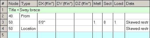
The Layout window is shown below:
The graphics is shown below:
The rendered graphics is shown below: