Snow & Ice – ASCE/SEI 7-22
Guidelines for computing the Snow & Ice Loads as per “ASCE/SEI 7-22: Minimum Design Loads and Associated Criteria for Buildings and Other Structures” are explained below.
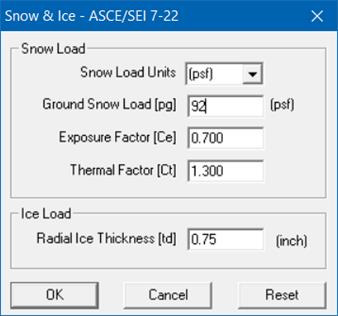
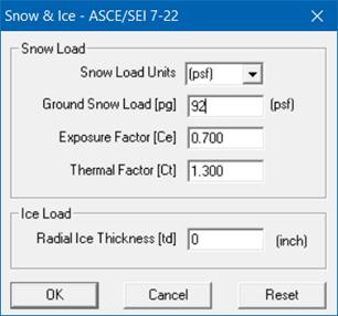
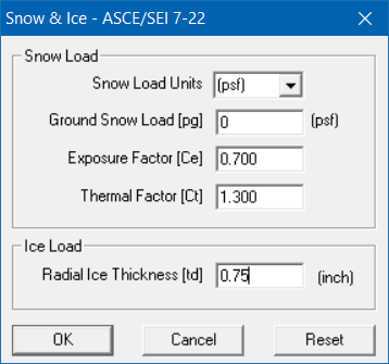
Snow and Ice loads can be included in CAEPIPE Analysis by inputting the parameters shown in the dialog above.
Note: Both Snow & Ice loads can be applied simultaneously in the stress model by inputting columns “Snow Load” as “Y” as well as “Ice Load” as “Y” in Load input dialog.
Structure Occupancy Category (Risk Category):
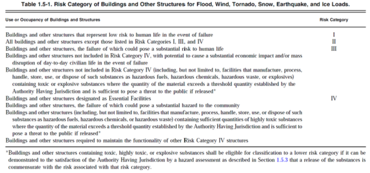
Table 1.5-1 of ASCE/SEI 7-22 provides the Risk Category of Buildings and Other Structures for Flood, Wind, Snow, Earthquake, and Ice Loads Structure. Depending on your project specification, Risk Category can be identified by referring to the table provided below.
Site Class:
Based on the site soil properties, site shall be classified as Site Class A, B, C, D, E & F.
Refer Chapter 20 of ASCE/SEI 7-22 for details on Site Class. Depending on your project specification, Site Class can be determined.
Note: Para. 11.4.2.1 of ASCE/SEI 7-22 states that “Where the soil properties are not known in sufficient detail to determine the site class, risk targeted maximum considered earthquake (MCER) spectral response accelerations shall be based on the most critical spectral response acceleration at each period of Site Class C, Site Class CD, and Site Class D, unless the Authority Having Jurisdiction determines, based on geotechnical data, that Site Class DE, E, or F soils are present at the site”.
Snow Lods – ASCE/SEI 7-22
Ground Snow Loads (Pg)
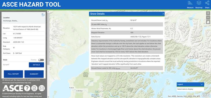
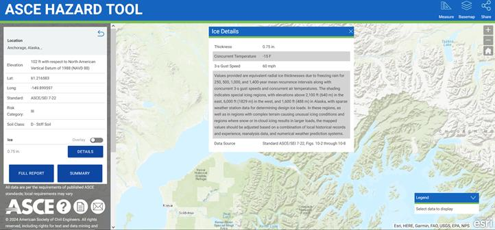
ASCE maintains a website https://ascehazardtool.org/ with which the Ground Snow Load (Pg) can be retrieved based on Site Address or Site latitude & longitude, Risk Category and Site Class.
For example, for Anchorage, Alaska, the value of Pg is retrieved as 92 lb/ft2 with Structure Occupancy Category III and Site Class D from the link https://ascehazardtool.org/ as shown below.
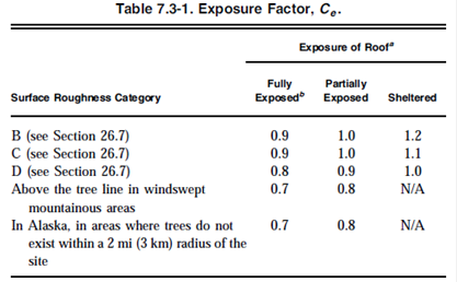
Exposure Factor (Ce)
Table 7.3-1 of ASCE/SEI 7-22 provides the Exposure Factor (Ce) with reference to the Surface Roughness Category and Exposure of Roof.
For example, in Alaska, in areas where trees do not exist within a 2 mi radius of the site that is fully exposed, Exposure Factor (Ce) is 0.70.
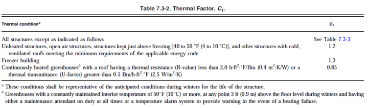
Thermal Factor (Ct)
Table 7.3-2 of ASCE/SEI 7-22 provides the Thermal Factor (Ct) with reference to the Thermal condition of the site.
For example, for a Freezer Building, Thermal Factor (Ct) is 1.3.
When the required parameters are input, then CAEPIPE computes and applies the snow loads in the stress model. Given below is a sample calculation of Snow load for a NS 10” Pipe with an Insulation Thickness of 2”.
|
Snow Load - Chapter 7 of ASCE/SEI 7-22
| ||
|
Ground Snow Load [Pg] =
|
92.00
|
lb/ft2
|
|
Exposure Factor [Ce] =
|
0.70
|
|
|
Thermal Factor [Ct] =
|
1.30
|
|
|
Pipe Diameter [OD] =
|
10.750
|
inches
|
|
Insulation Thickness [Thk] =
|
2.00
|
inches
|
|
Snow Load Calculation
| ||
|
Diameter [D] = OD + 2 * THK =
|
1.23
|
feet
|
|
Base [b] = 0.934 * D =
|
1.15
|
feet
|
|
Snow Density = γ =0.13*Pg + 14 <= 30 lb/ft3
|
25.96
|
lb/ft3
|
|
Snow load on roof [Pf] = 0.7*Ce*Ct*Pg =
|
58.60
|
lb/ft3
|
|
height = Pf/γ =
|
2.26
|
feet
|
|
0.73*Pf/γ =
|
1.65
|
feet
|
|
If D < 0.73* Pf/r, then Snow Load should be computed as per Figure 7.13-2(a) of ASCE/SEI 7-22
If D > 0.73* Pf/r, then Snow Load should be computed as per Figure 7.13-2(b) of ASCE/SEI 7-22
| ||
|
Snow Load as per Figure 7.13-2(a) of ASCE/SEI 7-22
| ||
|
height = 1.37 * D =
|
1.68
|
feet
|
|
Snow Load as per ASCE/SEI 7-22 = (1/2)*D*h*γ *1.00 =
|
26.87
|
lb/ft
|
Inputting the above manually computed “Snow Load” as an “Additional Weight” in CAEPIPE vs inputting the Snow load parameters for a given layout should produce the same results.
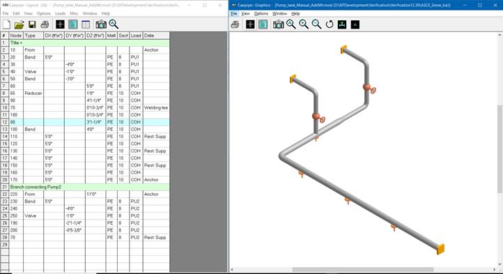
To demonstrate, two CAEPIPE models “Pump_tank_Manual_Snow_AddWt.mod” and “Pump_tank_ASCE_Snow.mod” were created in Version 13.00 with identical layouts as shown below.

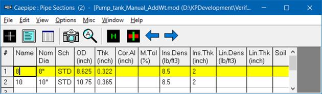
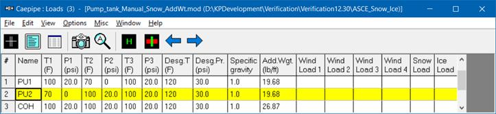
In model “Pump_tank_Manual_Snow_AddWt.mod”, Snow Loads were computed manually as per Chapter 7 of ASCE/SEI 7-22 for NS 10” and NS 8” Pipes with 2” Insulation Thickness as “26.87 lb/ft” and “19.68 lb/ft” respectively and entered them as “Additional Weight” under the “Loads” as shown in the figure above.
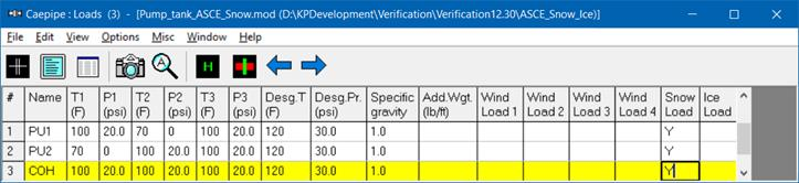
On the other hand, in model “Pump_tank_ASCE_Snow.mod”, parameters for Snow Load are input as shown in the dialog box through CAEPIPE Layout Window > Misc > Snow & Ice – ASCE/SEI 7-22. After entering the parameters, the Snow Loads are assigned to the Loads by inputting the “Snow Load” column as “Y” as shown below.
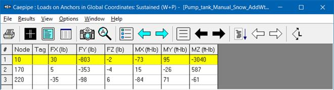
From the Support Loads for Sustained Load case results of the two models, it is observed that the results are identical confirming its implementation.

Ice Lods – ASCE/SEI 7-22
Radial Ice Thickness (td)
ASCE maintains a website https://ascehazardtool.org/ with which the Radial Ice Thickness (td) can be retrieved based on Site Address or Site latitude & longitude, Risk Category and Site Class.
For example, for Anchorage, Alaska, the value of “td” is retrieved as 0.75” with Structure Occupancy Category III and Site Class D from the link https://ascehazardtool.org/ as shown below.
When the required parameter is input, CAEPIPE computes and applies the Ice loads in the stress model. Given below are sample calculations of Ice load for a NS 10” and NS 8” Pipe with an Insulation Thickness of 2”.
|
Ice Load - Chapter 10 of ASCE/SEI 7-22
| ||
|
Radial Ice Thickness [td] =
|
0.75
|
inches
|
|
Density of Ice as per ASCE/SEI 7-22 [γ] =
|
56.00
|
lb/ft3
|
|
Pipe Diameter [OD] =
|
10.750
|
inches
|
|
Insulation Thk [Thk] =
|
2.00
|
inches
|
|
Ice Load Calculation
| ||
|
Diameter [D] = OD + 2 * THK =
|
1.23
|
feet
|
|
Ice Load as per Section 10.4.1 of ASCE/SEI 7-22
| ||
|
Area (Ai) =
|
0.25
|
ft2
|
|
Ice Load = Ai * γ =
|
14.20
|
lb/ft
|
|
Ice Load as per ASCE/SEI 7-22 =
|
14.20
|
lb/ft
|
|
Ice Load - Chapter 10 of ASCE/SEI 7-22
| ||
|
Radial Ice Thickness [td] =
|
0.75
|
inches
|
|
Density of Ice as per ASCE/SEI 7-22 [r] =
|
56.00
|
lb/ft3
|
|
Pipe Diameter [OD] =
|
8.625
|
inches
|
|
Insulation Thk [Thk] =
|
2.00
|
inches
|
|
Ice Load Calculation
| ||
|
Diameter [D] = OD + 2 * THK =
|
1.05
|
feet
|
|
Ice Load as per Section 10.4.1 of ASCE/SEI 7-22
| ||
|
Area (Ai) =
|
0.22
|
ft2
|
|
Ice Load = Ai * r =
|
12.26
|
lb/ft
|
|
Ice Load as per ASCE/SEI 7-22 =
|
12.26
|
lb/ft
|
Inputting the above manually computed “Ice Load” as an “Additional Weight” in CAEPIPE vs inputting the Ice load parameter for the two identical layouts should produce the same results.
To verify the above, two CAEPIPE models “Pump_tank_Manual_Ice_AddWt.mod” and “Pump_tank_ASCE_Ice.mod” were created in Version 13.00 with identical layouts as shown below.
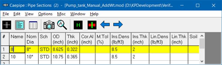
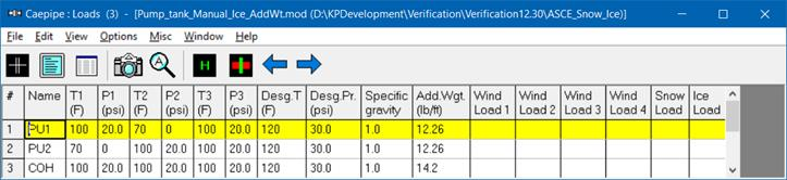
In model “Pump_tank_Manual_Ice_AddWt.mod”, Ice Loads were computed manually as per Chapter 10 of ASCE/SEI 7-22 guidelines for NS 10” and NS 8” Pipes with 2” Insulation Thickness as “14.2 lb/ft” and “12.26 lb/ft” respectively and entered them as “Additional Weight” under the “Loads” as shown above.
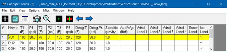
On the other hand, in model “Pump_tank_ASCE_Ice.mod”, parameter for Ice Load is input as shown in the dialog box through CAEPIPE Layout Window > Misc > Snow & Ice – ASCE/SEI 7-22. After entering the parameter, the Ice Load is assigned to the “Loads” by inputting the “Ice Load” column as “Y” as shown below.
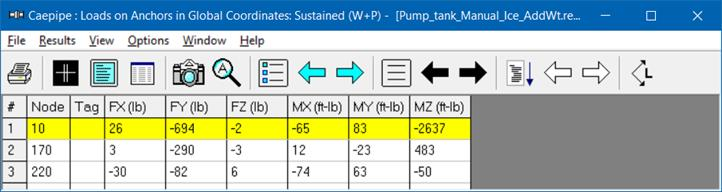
From the Support Loads for Sustained Load case results of the two models, it is observed that the results are identical confirming its implementation.