Spider
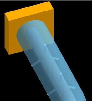
Use a spider (also called a spacer) to connect the coincident nodes of a jacketed pipe (i.e., the node on the core pipe and the corresponding node on the jacket pipe). The spider acts as an internal guide. At the spider location, the local x-axis is calculated along the pipe direction. The spider connects the local y and z translations for the core and jacket nodes. It prevents any radial movement but allows sliding, rotating and bending movement between core and jacket pipes. No gap is allowed between the core pipe and the spider. See section on Jacketed pipe for related information.
“Spider” is used to center the core pipe within the jacket pipe. The spacing between two adjacent Spiders should be such that the outer surface of the core pipe in “deformed operating state” does not “touch” the inner surface of the surrounding jacket pipe anywhere in between two adjacent Spiders. This can be accomplished by inserting “intermediate nodes” between two adjacent Spiders and by making sure that the Displacements at those intermediate nodes under normal operating conditions are well below the annular gap between the outer surface of the core pipe and the inner surface of the jacket pipe.
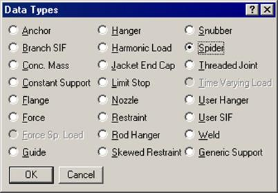
A spider is input at a jacketed pipe node by typing “sp” in the Data column or selecting “Spider” from the Data Types dialog.
Starting Version 10.30, CAEPIPE has the built-in feature to calculate g-load values using the procedure given in ASCE/SEI 7-16 as described below.