Static Seismic Load – ANSI A58.1-1988
The procedure from ANSI A58.1-1988, “Minimum Design Loads for Buildings and Other Structures,” is used in the below example to calculate the g-load values for input into CAEPIPE.
Piping is assumed to be equivalent to equipment, thus giving a force coefficient, Cp as 0.3.
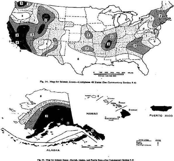
1. First, based on the map below (Contiguous 48 States+Alaska/Hawaii/Puerto Rico), identify the seismic zone and its corresponding coefficient (Z).
|
Seismic Zone
|
Coefficient Z
|
|
4
|
1.0000
|
|
3
|
0.7500
|
|
2
|
0.3750
|
|
1
|
0.1875
|
|
0
|
0.1250
|
Determine the Importance Factor, I as follows:
I = 1.5, For piping required in an emergency or piping with contents representing a significant hazard to human life
I = 1.0, For other piping
Calculate the acceleration (g’s) as 0.3 × Z × I
Example:
For a power plant required to operate in an emergency, located in Anchorage, Alaska, calculate the design earthquake load coefficient for piping required to operate the plant.
1. From the map above, the seismic zone is 4; from the table above, the corresponding Coefficient Z is 1.0.
2. For piping required to operate in an emergency, the Importance Factor I = 1.5.
3. Calculate horizontal acceleration as 0.3 × 1.0 × 1.5 = 0.45g, Vertical g-load (g) = 0.75 * horizontal acceleration = 0.34g.
The above accelerations need to be applied in the desired horizontal and vertical directions as long as the piping system is predominantly routed at grade level.