Tees
Physical tees, even though integral components, are not modeled as such in CAEPIPE. Instead, they are modeled as three pipes coming together at a common node.
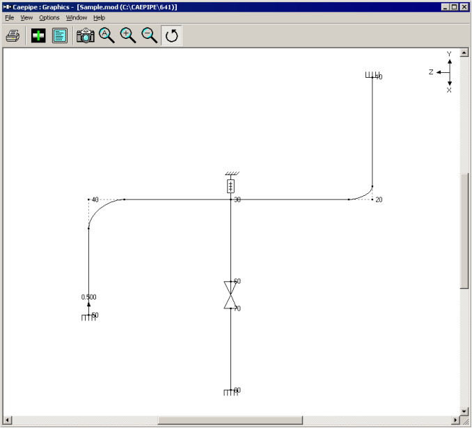
In this figure, you can see that three pipe elements (20-30, 30-40, and 30-60) come together at node 30 to form a tee.
Modeling
The method of modeling is as simple as its representation.
Step 1:
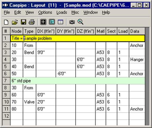
You could model the pipe run first from 20 to 30 (1st element), then from 30 to 40 (2nd element), and finally, from 30 to 60 (3rd element). See example layout window below.
Alternately, you could model from 20 – 30 – 60, and then 30 – 40. Or from 60 – 30 – 20, and then 30 – 40. Modeling order is immaterial to analysis (but sometimes complicates the merge files process. See Merge under Layout window > Merge in the User’s Manual).
Step 2:
There is one final step remaining. You need to designate the type of tee connection it is. In this example, the tee is a “Welding Tee”. So, on any row that contains node 30 (i.e., row #4 or row #8), type “Br” (Branch SIF) and select “Welding Tee” from the drop down list. Since row #4 already has a hanger specified, you can use row #8 to specify the Branch SIF.
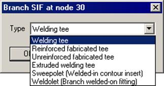
The shown Branch SIF list is piping code-dependent. In other words, the list of tee types shown comes from the selected piping code that dictates how an SIF for each of the listed tee types is calculated. See Section titled “Piping Code Compliance” from the Code Compliance Manual for information on Branch SIFs for different piping codes.
Based on a more rigorous analysis, if you have another more accurate SIF value for a joint you want to insert (instead of the code’s), then skip Step (2) above and use User-SIF data type at the same node to input your own SIF.
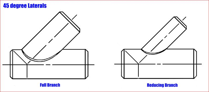
For 45° laterals, a piping code committee member opines as follows:
Use the SIF for an unreinforced fabricated tee and evaluate the branch stress using the section modulus of the branch. The connection footprint on the run pipe itself has a section modulus greater than the branch section modulus and this will compensate for the unreinforced fabricated tee SIF which should be lower than the unreinforced fabricated lateral SIF. Ignore the fact that a reduced outlet branch connection requires an “effective section modulus” in accordance with ASME B31.1 (2014) Para. 104.8.4(C) or ASME B31.3 (2014) Para. 319.4.4(c) and just calculate the intensified stress as the unreinforced fabricated tee SIF x the branch moment / branch section modulus (whether you use the SIF times the resultant moment approach of B31.1 or the in-plane and out-plane SIFs times the in-plane and out-plane moments, respectively, approach of B31.3, use the same philosophy of ignoring the “effective modulus.”
Pay particular attention to the fabrication of the lateral making sure that the Code required cover fillet dimensioned t(c) in ASME B31.1 (2014) Fig. 127.4.8(D)(a) or ASME B31.3 (2014) Fig. 328.5.4D(1) meets the required size. If the cover fillet is larger than t(c), that improves the lateral SIF. The figures and dimensions shown are a bit unfortunate, especially for a lateral because a strict reading of the Code would seem to require a bigger weld on the obtuse side of the branch and a smaller weld on the acute side of the branch when just the opposite is true. Having a constant cover fillet weld leg length all around the branch would improve the requirement and the committee has been working on that. Personally, I think the larger the run and branch pipes are, the larger the cover fillet should be. Ask for or calculate whether area replacement requirements ASME B31.1 (2014) Para. 104.3.1(D) or ASME B31.3 (2014) Para. 304.3.3 are met noticing that the required reinforcement for a lateral is greater by the factor (2 - sin alpha).