Analysis
The Analysis Options dialog is shown. Here you can specify analysis options related to piping codes, temperature, pressure, dynamic analysis, etc., in various tabs of the dialog.
Code
On this tab you can choose the piping code and also set options for that piping code.
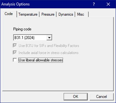
Select a piping code from the “Piping code” drop-down combo box. The codes listed below are from Version 15.00:
|
· ASME B31.1 (2024) - Power Piping
|
|
· ASME B31.1 (1967) - Power Piping
|
|
· ASME B31.1 (1973) - Power Piping
|
|
· ASME B31.1 (1977) - Power Piping
|
|
· ASME B31.1 (1980) - Power Piping
|
|
· ASME B31.3 (2024) - Process Piping
|
|
· ASME B31.4 (2022) - Pipeline Transportation Systems for Liquids and Slurries
|
|
· ASME B31.5 (2022) - Refrigeration Piping and Heat Transfer Components
|
|
· ASME B31.8 (2025) - Gas Transmission and Distribution Piping Systems
|
|
· ASME B31.9 (2020) - Building Services Piping
|
|
· ASME B31.12 IP (2023) - Hydrogen Piping
|
|
· ASME B31.12 PL (2023) - Hydrogen Pipelines
|
|
· ASME NM.1 (2022) - Thermoplastic Piping Systems
|
|
· ASME NM.2 (2022) - Glass-Fiber-Reinforced Thermosetting-Resin Piping Systems (GRP/FRP)
|
|
· ASME Class 2 (1980) - ASME Section III, Subsection NC - Class 2
|
|
· ASME Class 2 (1986) - ASME Section III, Subsection NC - Class 2
|
|
· ASME Class 2 (1992) - ASME Section III, Subsection NC - Class 2
|
|
· ASME Class 2 (2015) - ASME Section III, Subsection NC - Class 2
|
|
· ASME Class 2 (2017) ASME Section III, Subsection NC - Class 2
|
|
· ASME Class 2 (2021) - ASME Section III, Subsection NC - Class 2
· ASME Class 2 (2023) - ASME Section III, Subsection NC - Class 2
|
|
· ASME Class 3 (2017) - ASME Section III, Subsection ND - Class 3
|
|
· ASME Class 3 (2021) - ASME Section III, Subsection ND - Class 3
· ASME Class 3 (2023) - ASME Section III, Subsection ND - Class 3
|
|
· ISO 14692-3 (2017) - Petroleum and Natural Gas Industries - Glass Reinforced Plastics (GRP/FRP) Piping
|
|
· EN 13480 (2020) - Metallic industrial piping
|
|
· EN 13941 (2021) - District heating pipes
|
|
· BS 806 (1986) - Construction of Ferrous Piping Installations for and in Connection with Land Boilers (British)
· DNV-ST-F101 (2021) – Submarine pipeline systems
|
|
· IGEM (2012) - Institution of Gas Engineers and Managers (IGEM) IGE/TD/12 Edition 2 (UK)
|
|
· Norwegian (1983) - Process design
|
|
· Norwegian (1990) - Process design
|
|
· RCC-M (1985) - Design and Construction Rules for Mechanical Components of PWR Nuclear Islands (French)
|
|
· RCC-M (2018) - Design and Construction Rules for Mechanical Components of PWR Nuclear Islands (French)
|
|
· RCC-M (2020) - Design and Construction Rules for Mechanical Components of PWR Nuclear Islands (French)
|
|
· RCC-M (2022) - Design and Construction Rules for Mechanical Components of PWR Nuclear Islands (French)
|
|
· CODETI (2013) - CODE DE CONSTRUCTION DES TUYAUTERIES INDUSTRIELLES (French)
|
|
· Stoomwezen (1989) - Dutch Power piping code
|
|
· Swedish (1978) – Swedish piping code
|
|
· Z183 (1990) - Oil Pipeline Systems (Canadian)
|
|
· Z184 (1992) - Gas Pipeline Systems (Canadian)
|
|
· Z662 (2023) - Oil & Gas Pipeline Systems (Canadian)
|
|
· NONE (for aircraft, aerospace & defence industries)
|
Notes:
|
For piping code = NONE, Equipment Qualification and Dynamic Analysis (Harmonic Analysis, Time History Analysis and Force Spectrum Analysis) are disabled in CAEPIPE. Hence, changing the analysis code to NONE from other code will delete all data related to Equipment, Harmonic load, Time History and Force Spectrum from the stress model without any warning.
|
· When the selected piping code is “None,” a “Static analysis” load case, which includes weight, pressure, thermal, cold spring, static seismic and wind loads, all applied at the same time, is available for analysis. No dynamic loads (time history, response spectrum, etc.) are included. For “Piping code = None” and a non-FRP material, the in-plane and out-of-plane Stress Intensification Factors (SIF) for a 90° bend/elbow are taken to be the same as those computed using ANSI B31.3. For a bend with bend angle less than 90°, the in-plane and out-of-plane SIFs are computed using the procedure given in ASME/BPVC Section III, Division1, Case N-319-2 “Alternate Procedure for Evaluation of Stresses in Butt Welding Elbows in Class 1 Piping.”
· For some piping codes, you need to select or input an additional option (such as Design Factor for B31.8, equation level for ASME Class 2, ASME Class 3, ASME B31.1 (1973, 1977 & 1980) and RCC-M, Location Factor for Z183 and Z184, Occasional load factor for EN13480-3). These are shown below.


Use B31J for SIFs and Flexibility Factors
This option visible only if the Piping Code selected for Analysis is ASME B31.1/ASME B31.3/ASME B31.4/ASME B31.5/ASME B31.8/ASME B31.9/ASME B31.12.
By checking this box, you can instruct CAEPIPE to compute Stress Intensification Factors (SIFs) and Flexibility Factors (FFs) as per ASME B31J.
When this option is not checked, then CAEPIPE will compute SIFs and FFs as per Appendix D of the ASME code selected for Analysis.
For a few ASME B31.x codes, SIFs and FFs have to be computed as per B31J. In such cases, this option will be disabled for the user to modify. For example, for ASME B31.1 (2020 or later), SIFs and FFs should be computed using B31J. Hence, this option is disabled for the user from modifying.
For further details on implementation, refer to CAEPIPE Code Compliance Manual.
Include axial force in stress calculations
By checking or un-checking this box, you can include or exclude axial force in stress calculations (F/A term). This option applies to all stresses (Sustained, Occasional and Expansion) and is provided since many piping codes do not clearly mandate the axial term’s inclusion. When included, CAEPIPE includes the axial term F/A (where F=axial load, A=Pipe cross-sectional area)in its calculation of all stress equations such as  ,
,  and
and .
.
Note that this option may be turned on depending on the code requirements.
Combine stresses as per Max. Distortion Energy Theory
For B31.4 and B31.8 piping codes, the buried piping stress are combined as per Maximum Shear Stress Theory when this option is turned OFF. On the other hand, when this option is turned ON, then the buried piping stresses are combined as per Maximum Distortion Energy Theory.
Use Liberal Allowable Stresses
For B31.1, B31.1(1967), B31.3, B31.5, B31.12 and CODETI piping codes, the allowable expansion stress may be increased by a difference between the allowable sustained stress and the actual sustained stress times the stress range reduction factor. See Thermal Expansion Stress Range or equivalent under each piping code in CAEPIPE Code Compliance Manual.
A piping code committee member opines as follows.
Perhaps the term “liberal allowable” is not the best to describe the allowable. The allowable stress in B31.1 Eq. 13, i.e.,  , can be used anytime. The only prerequisite is knowing the
 stresses, which will only be the case after the supports are known or implicit. The Eq. 1 allowable stress,
  , is the allowable stress traditionally used in the flexibility analysis when no supports other than the equipment anchors are known. The flexibility analysis is used to determine whether the layout of piping between the equipment anchors is adequate. The displacements determined in the flexibility analysis will allow the designer to devise the pipe weight supports to interfere with the flexibility of the pipe as little as possible, i.e., the designer will use rigid supports where the piping does not move much, use variable springs where the piping moves a small amount (most typically 1/4” to 4”), and use constant springs where the movement is great (again, typically over 4”). For lateral loads the same concept as used for the pipe weight supports is used for the lateral supports, i.e., if lateral displacements are small, rigid supports may be used, for larger lateral movements, gapped or shock suppressor supports are used (although shock suppressor supports require considerable maintenance attention and in the long run are usually not preferable to gapped supports).
General Note on Thermal Allowable Calculation for All Piping Codes
Cold allowable (Sc) and Hot allowable (Sh) stresses used in thermal stress calculations are calculated as follows for all piping codes:
· For Expansion Cases T1 through T10, Cold allowable (Sc) is taken at Minimum (Tref, Tn) and Hot allowable (Sh) is at Maximum (Tref, Tn), where n = 1 to 10.
· For Thermal Ranges Tx-Ty, Cold allowable (Sc) is at Minimum (Tx, Ty) and Hot allowable (Sh) is at Maximum (Tx, Ty), where x = 1 to 10 and y = 1 to 10 and x is not equal to y.
The specifics are summarized for each B31.x piping code under the title “Thickness and Section Modulus used in Weight, Pressure and Stress Calculations for ANSI B31.x Codes” of the CAEPIPE Code Compliance Manual.
Temperature
On this tab you can set options related to thermal loads.

Reference Temperature
Input the reference temperature here, usually 70°F (21.1°C) corresponding to the installation temperature. CAEPIPE uses this temperature to lookup material properties table for the elastic modulus (see subsection titled “Elastic Modulus” below) and to calculate thermal stress ranges such as (T1 – Tref), (T2 – Tref), (T1 – T2) = (T1 – Tref) – (T2 – Tref), etc.
Number of Thermal cycles (N)
CAEPIPE uses this number (= 7000 by default) to determine the stress range reduction factor, (f or U), which is used to reduce the allowable expansion stress range, .
The reduction factor “f” used by CAEPIPE for different piping codes are described / listed in the Code Compliance Manual.
The typical equation for calculating thermal expansion stress range (e.g., for B31.1 code) is
where
Note:
|
When the Simplified Fatigue Evaluation is turned ON, then the Number of full displacement cycles (N) computed as per the Simplified Fatigue Evaluation will internally overwrite this Number of Thermal Cycles (N) input by the user.
|
Number of Thermal Loads
You can enter up to 10 thermal loads. This feature must be first set through Layout window > Options > Analysis > Temperature. The maximum number of thermal loads that one or more elements of a stress model can experience during operation should be input for the Number of Thermal Loads. Up to 10 operating temperatures may be applied as part of Load (along with 10 operating pressures) under Misc menu > Loads.
In addition to 10 thermal loads and 10 pressures, you can also enter the Peak Pressure and Peak Temperature through the fields Desg.T and Desg.P respectively. Refer to Section titled “Load” in the Technical Reference Manual for details on Peak Temperature and Peak Pressure.

This also enables you to enter 10 temperatures under Misc menu > Beam Loads.

Additionally, up to 10 specified thermal displacements can be entered for Anchor, Generic Support and Nozzle data types.

Thermal load case results can be calculated as the difference between the Operating and the Sustained load cases, i.e., the thermal load case is not solved independently. This is the recommended procedure to solve thermal cases (T1 through T10) especially when nonlinearities (limit stops, friction, etc.) are present.
When a model has no nonlinearities, the forces, moments and displacements at nodes add up (i.e., Sustained load + Thermal load = Operating load). When a nonlinearity is present, each load case can be solved independently, i.e., the numbers are not added from Sustained (W+P) to Thermal (T1) to get Operating (W+P+T1); in other words, the results do not always add up. In the past, this used to be the only method of solving when nonlinearities were present. However, now you can use the new (recommended) option called “Thermal = Operating – Sustained”, which is in line with the requirement that thermal stress range is to be calculated between two actual thermal states. Use it to solve for the thermal case as the difference between Operating and Sustained cases, which will also ensure that sustained and thermal case results add up to operating case results.
Solve Thermal case
Results for the thermal load case are obtained by solving this case independently. This option is generally not recommended. See above discussion.
Elastic Modulus
User can select one of the two options available in CAEPIPE (as given below).
· Use temperature dependent modulus
· Use modulus at reference temperature
When the option “Use temperature dependent modulus” is chosen in CAEPIPE, then CAEPIPE computes the elastic modulus at the temperature under consideration (Ehot) while forming the Global stiffness matrix for each load case, i.e., at temperature T1 for Operating 1, T2 for Operating 2, … T10 for Operating 10. In short, CAEPIPE uses hot modulus (Ehot) to compute the Displacements, Element Forces & Moments, Support Loads and Stresses when the option “Use temperature dependent modulus” is chosen.
On the other hand, when the option “Use modulus at reference temperature” is chosen in CAEPIPE, then CAEPIPE computes the elastic modulus at “Reference Temperature (Tref)” (hereafter referred to as Ecold) while forming the Global stiffness matrix for each load case. In short, CAEPIPE uses cold modulus (Ecold) to compute the Displacements, Element Forces & Moments, Support Loads and Stresses when the option “Use modulus at reference temperature” is chosen.
Note:
“Expansion Stresses” for Restrained portion of piping (i.e., buried portion) for the piping code Z662 are calculated using elastic modulus at reference temperature (Ecold) irrespective of the option (among the above two options) chosen by the user for Elastic Modulus. On the other hand, for Restrained portion of piping, Displacements, Element Forces & Moments, Support Loads and Stresses (excepting Expansion Stresses) are computed using the elastic modulus option chosen by the user, i.e., Ehot or Ecold.
For Unrestrained portion of piping (portion not buried), for the piping code Z662, Displacements, Element Forces & Moments, Support Loads and Stresses are computed using the elastic modulus option chosen by the user, i.e., Ehot or Ecold.
As per para. 402.2.2 of ASME B31.4 (2022) and para. 832.2 (g) of ASME B31.8 (2022), flexibility calculations shall be based on the modulus of elasticity at ambient temperature, i.e., modulus at reference temperature (Ecold). Hence, "Use modulus at reference temperature" (available through CAEPIPE Layout > Options > Analysis > Temperature) is set as "default" and is disabled for user to modify when B31.4 or B31.8 code is selected. In short, for both Restrained and Unrestrained portions of piping, Ecold is used in CAEPIPE to calculate Displacements, Element Forces & Moments, Support Loads and Stresses for B31.4 and B31.8 codes.
As per para. 519.4.5(a) of ASME B31.5 (2022) code, Bending and Torsional stresses shall be computed using the as-installed modulus of elasticity, i.e., modulus at installation temperature (Ecold). Hence, "Use modulus at reference temperature" (available through CAEPIPE Layout > Options > Analysis > Temperature) is set as "default" and is disabled for user to modify when ASME B31.5 code is selected.
Similarly, as per para. 12.2.7.2 of EN 13480-3 (2020), value of the modulus of elasticity (Et) used for flexibility analysis shall be the value taken at the temperature of the piping load under consideration, i.e., modulus at temperature under consideration (Ehot). Hence, "Use temperature dependent modulus" (available through CAEPIPE Layout > Options > Analysis > Temperature) is set as "default" and is disabled for user to modify when EN 13480 code is selected.
Pressure
On this tab you can set options related to pressure loads.

Pressure Stress
The longitudinal pressure stress may be calculated as:
However, for B31.8 code, the pressure stress term is not an option.
Peak Pressure Factor
For occasional loads (seismic, spectrum, and wind), the pressure p used in the longitudinal pressure stress is multiplied by a peak pressure factor.
Starting with Version 15.00, when the option “Compute peak pressure factor using (Ppeak/Pmax)” is enabled, CAEPIPE automatically calculates the peak pressure factor for each element as the ratio of the Peak Pressure input to the maximum Operating Pressure (P1 through P10).
Note:
When a model created in an earlier CAEPIPE version is imported into Version 15.00 or later, the “Compute peak pressure factor using (Ppeak/Pmax)” option is disabled by default.
If this option is subsequently enabled for an imported model, the occasional stresses computed in Version 15.00 may differ from those calculated in earlier CAEPIPE versions.
Bourdon Effect
Internal pressure will expand the pipe cross-section radially outward (i.e., bulge out) thereby contracting the length of the pipe due to Poisson’s effect. On the other hand, external pressure will contract the pipe cross-section radially inward (i.e., shrinking inwards) thereby elongating the pipe length again due to Poisson’s effect. On the contrary, due to end-cap force developed by pressure, straight pipe elements will elongate for internal pressure and contract for external pressure. These physical phenomena are included in CAEPIPE calculations when the "Bourdon effect" button is turned ON. Pipe stresses and support loads generated due to such "Bourdon effect" deformations are generally considered as "Secondary Stresses and Support loads" and normally considered as part of the thermal expansion load case.
Therefore, this effect is treated as an expansion load and by default included in the expansion and operating load cases when the option “Expansion Load Cases” is selected under the option “Bourdon”. It is not applied to the sustained and occasional load cases.
On the other hand, if the option “Sustained Load Cases” under the option “Bourdon” is selected, then the Bourdon effect is treated as a sustained load and hence, included in the sustained and operating load cases. It is not applied to the expansion load case.
Note:
For CAEPIPE versions earlier than 13.00, set an environment variable “BOURDONP” with its value as YES to add the Bourdon effect to the sustained and operating load cases.
For a straight pipe, the following equation is used.
where
Pressure Correction for Bends (Pressure stiffening effect)
Pressure correction for bends is different from and unaffected by Bourdon effect. In large diameter thin-wall bends, pressure can significantly affect their flexibility and SIF. If pressure correction for bends is used: the Flexibility of the bend is divided by
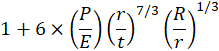
and the SIF for the bend is divided by

where
It is recommended that this option be turned ‘ON’ whenever the internal or external pressure is high, so that the stiffening of the bend due to internal or external pressure is considered in the analysis. In other words, when a thin-walled pipe bend is bent by bending moments at its two ends, the bend will ovalize and increase its flexibility. Internal or external pressure will reduce this bend ovalization, thereby increasing its stiffness.
Pressure correction decreases the flexibility of the piping system (by increasing the stiffness of the system because of the stiffened elbows). Hence, the system frequencies (in modal analysis) tend to increase.
This pressure correction option is provided for all piping codes available in CAEPIPE.
Dynamics
On this tab you can set options related to dynamic analysis.

Cutoff Frequency / Number of Modes
These two options jointly control how the modal analysis routine works to extract the natural frequencies. Frequency(Hertz)and the chosen number of modes will determine the minimum number of modes extracted. The modal analysis will terminate either when the number of modes requested has been extracted or after extracting an additional frequency above the specified cutoff frequency value, whichever occurs first.
For earthquake analysis, a typical value for cutoff frequency is 33 Hz. The maximum frequency you can input is 9999 Hz.
When the selected piping code is “None,” and the model contains nonlinearities (limit stops, certain expansion joints), a static analysis for a given model with and without a g-load input may produce different frequencies depending upon the status of the nonlinearities due to the presence or absence of the g-load in the static load case.
Include Missing Mass Correction
Missing mass correction to the response spectrum analysis can be included using this check box. See topic by the same name in the Technical Reference Manual.
Use Friction in Dynamic Analysis
Friction is optional in dynamic analysis. If friction is included in dynamic analysis, the global stiffness matrix arrived at upon completion of the iterative calculations for the first operating case (W+P1+T1) is used to compute frequencies and mode shapes for the piping system.
When this option is turned ON, then CAEPIPE uses the equivalent Stiffness corresponding to the frictional force (= friction coefficient x normal force) at the non-linear support arrived at the last iteration of ‘STATIC’ or ‘Operating 1’ Load Case.
On the contrary, when this option is turned OFF, then CAEPIPE uses the friction stiffness as 0.0 (for the same nonlinear Support), while still using the Boundary conditions arrived at the last iteration of ‘STATIC’ or ‘Operating 1’ load case.
Similarly, for nonlinear elements, CAEPIPE uses the Friction Stiffness computed at the last iteration of ‘STATIC’ or ‘Operating 1’ Load Case when this option is turned ON. On the other hand, CAEPIPE uses the friction stiffness input at these elements when this option is turned OFF.
Misc
On this tab you can set miscellaneous options.
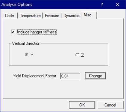
Include Hanger stiffness
When the checkbox is checked, CAEPIPE adds the hanger spring rates for variable spring and user hangers to the global stiffness matrix (recommended setting). Hanger spring rates for rod hangers (if active) are always included even when this checkbox is not checked.
If the checkbox is not checked, CAEPIPE does not include the hanger stiffnesses in the analysis (excepting for hanger spring rates for “active” rod hangers). Some users prefer this as it more closely matches “hand calculations.”
In the 1970s, performing pipe stress analysis on mainframe computers was expensive (about $1,000/run). So, pipe stress analysts would run a Thermal (T1) case alone first. Then, they would run a deadweight (DW) case with rigid supports at chosen hanger locations. Using the support loads and the hanger travel, analysts would select appropriate variable spring hangers from hanger manufacturer catalogs. To save on computing costs, they would not update the global stiffness matrix [K] with the hanger stiffnesses for the newly selected hangers because they would have to reanalyze the model which would cost more money. Many industrial plants built 30 or 40 years ago in the USA and presumably in other countries have pipe stress analyses done in this manner. These plants have archived such analysis reports that do not include hanger stiffnesses (as part of the global stiffness matrix [K]).
In later years, as and when the analysts for these plants needed to reanalyze those piping systems, they had to use modern programs like CAEPIPE. But, before they accepted the new results, they sometimes liked to verify that the new results (from CAEPIPE) matched the results from the old reports generated by the mainframe pipe stress analysis programs. This is why CAEPIPE provides the option “Do not include (or include) hanger stiffnesses.” It helps the engineers compare results from CAEPIPE with the old archived reports.
Today, with cheap PC computing power, there is no reason why hanger stiffnesses should be excluded from analysis. In fact, including hanger stiffnesses provides a more accurate picture of system behavior. As such, we recommend that you “include hanger stiffnesses” in every analysis.
Vertical Direction
You may specify either Y or Z as the vertical global axis for the model. If the vertical global axis is modified while building the stress layout, CAEPIPE will display the message as shown below. Press the button “Yes” to change the vertical axis and rotate the stress layout.

Pressing the button “No” will change the axis without rotating the model.
Equivalent Flange Pressure is calculated in accordance with Eq. 6.6.2-1 of EN 13480-3 (2020) and shown under “Flange Report” when the option “EN 13480 (2022)” is selected.
On the other hand, equivalent pressure is calculated in accordance with NC.3658.3 of ASME Section III Class 2 (2023) and shown under “Flange Report” when the option “ASME Class 2 (2023)” is selected.
Soil (in Buried piping analysis) is modeled with an initial stiffness and an ultimate load, after reaching which, displacement continues without a further increase in load (i.e., yield stiffness becomes zero). This field is grayed out by default for the user.
When you have a non-convergence problem during the Buried Piping Analysis, where it is not possible to change the layout or support scheme for the solution to converge, then you can try changing the initial soil stiffness by changing the Yield Displacement Factor from the default value of 0.04 up to 0.10 for Granular Soil (Cohesionless soil) and up to 0.20 for Clay or Stiff Soil (Cohesive soil) by pressing the button “Change”.