Element Forces
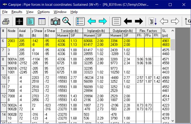
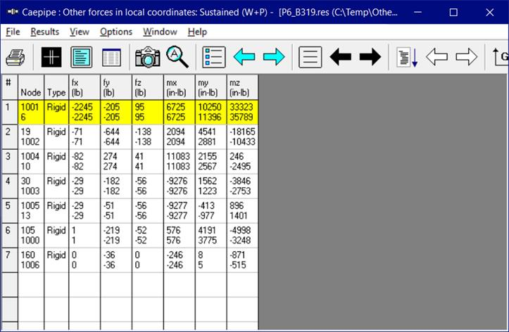
Forces and moments on all pipe elements are shown next. If you had other elements such as a valve or rigid, you can display forces and moments for them too by clicking on the Other Forces button on the toolbar.
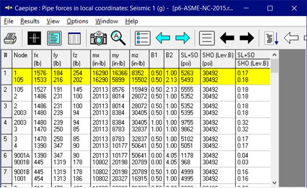
For ASME Class 2, ASME Class 3, ASME B31.1 (1973) and RCC-M codes, Element forces results will also show the Allowable Stress and Stress ratio for Expansion and Occasional load cases as shown below.
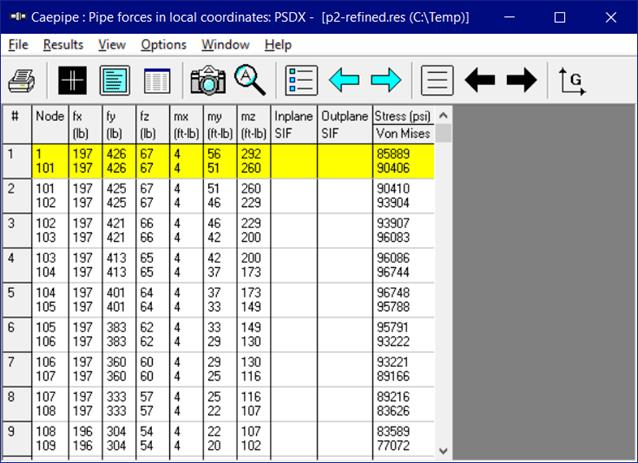
When Random Vibration Analysis is turned ON for NONE code, Element forces and moments results will show the Stress and the von Mises stress computed for each element for the selected load case such as PSDX or PSDY or PSDZ in the first line and second line respectively as shown below.
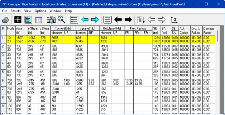
When the Detailed Fatigue Evaluation is enabled in the analysis for applicable piping codes, CAEPIPE will display additional columns titled Actual number of cycles (Act. Cycles), Number of cycles to failure (Cyc. to Failure) and Damage Factor related to Fatigue Evaluation as shown below.
The default view for forces and moments is in the local coordinate system. They can be shown in the global coordinate system too by clicking on the Global forces button (or selecting Global Forces command from the Results menu, hotkey: F7). When you select Global forces, the forces and moments are shown in global coordinates and the button changes in the same location (on the toolbar) to an “L” for Local forces. So, should you want to return to pipe forces in local coordinates, simply click again at the same location on the Local forces button.
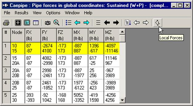
The convention in CAEPIPE is to display the headings for global forces and moments in uppercase (FX, FY, FZ, etc.) and display the headings for local forces and moments in lower case (fx, fy, fz, etc.).