IMPORT MBF
CAEPIPE can import model data from a text file, which may be created using a text editor and should have the extension: .mbf (model batch file). This text file may also be created for an existing model using the Export command from the Layout window.
To import a model, select the menu command File > Import from the Main window.
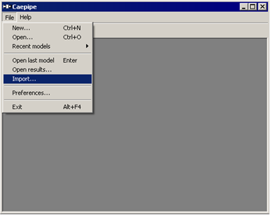
The Import Model dialog is shown.
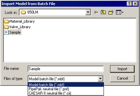
Select the model batch file (.mbf) and then click on the Import button. The batch file will be read and the corresponding model file (.mod) will be created and then shown in the Layout window which can be further modified or analyzed.
For detailed information on the .pnf and .cii file import capabilities please contact us at support@sstusa.com.
Command line operation
Dragging and dropping an .mbf file on CAEPIPE.exe will import, analyze and produce the results in .csv format and close the program. On the other hand, dragging and dropping the .mod file on CAEPIPE.exe will open the .mod file. Using the command line, you may have CAEPIPE analyze and produce a CSV results file thus:
C:\CAEPIPE> caepipe.exe sample.mbf (Enter)
The above command will produce a “sample.csv” file in the same folder as the .mbf file.
Format of .MBF
The input data is given in the following order. Except for the heading the start of each section is indicated by a keyword. The data for that section follow. Only the first three characters of the keyword are significant. See an example MBF at the end of this appendix.
Note:
CAEPIPE input for Concentrated Mass, Ball Joint, Rigid Element, Valve, Bellows, Slip Joint etc. require the “Weight” of that item to be input in lbf, kgf etc. and NOT its mass. So, whenever mass is required for a calculation as in the case of forming Mass matrix for dynamic analysis, or in calculating inertia force as (mass x acceleration) for static seismic analysis, CAEPIPE internally computes the mass for each item to be equal to (weight / g-value).
Similarly, for density of pipe, insulation and lining materials, CAEPIPE requires “Weight Density” to be input in lbf/in3, kgf/m3 etc. and NOT its mass density.
Keyword Data
Heading
VERSION MBF Version
OPTIONS Program options
FCURVE Fatigue Curves for detailed Fatigue evaluation
FCYCLE Actual number of Cycles for each expansion load case
MATERIAL Material properties
SOILS Soil properties
PIPE Section properties
LOADS Loads data
BMATERIALS Beam Materials
BSECTIONS Beam section properties
BLOADS Beam loads
SPCMS Spectrums (available in CAEPIPE Version 10.50 or later)
SPLVL Spectrum Levels (available in CAEPIPE Version 10.50 or later)
LAYOUT Layout data
PUMPS Pump data
COMPRESSORS Compressor data
TURBINES Turbine data
SEISMIC Seismic load
WIND Wind load
ALLOWABLES User allowable loads
PSDDT PSD Data for Random Vibration
PSDLD PSD Load for Random Vibration
Heading
Any number of heading lines may be given. Only the first will be used as Title in the CAEPIPE model.
VERSION
Mbf version. Example, 11.00
OPTIONS
Hanger design
HGRA Grinnell (Default)
HGRB Bergen-Paterson
HGRC Fee and Mason
HGRD Basic Engineers
HGRE Power Piping
HGRF Nordon
HGRG Carpenter and Paterson
HGRH NPS
HGRI PTP
HGRJ Corner and Lada
HGRK Elcen
Piping Code
B311 ASME B31.1
B311-67 USAS B31.1 (1967)
B311-73 ANSI B31.1 (1973)
B311-77 ASME B31.1 (1977)
B311-80 ASME B31.1 (1980)
B313 ASME B31.3
B314 ASME B31.4
B315 ASME B31.5
B318 ASME B31.8
B319 ASME B31.9
B3112 ASME B31.12 IP
B3112-PL ASME B31.12 PL
ASME-NM1 ASME NM 1
ASME-NM2 ASME NM 2
ASME ASME Section III, Class 2 (1980)
ASME-86 ASME Section III, Class 2 (1986)
ASME-92 ASME Section III, Class 2 (1992)
ASME-2015 ASME Section III, Class 2 (2015)
ASME-2017 ASME Section III, Class 2 (2017)
ASME-2021 ASME Section III, Class 2 (2021)
ASME-2023 ASME Section III, Class 2 (2023)
ASME-ND-2017 ASME Section III, Class 3 (2017)
ASME-ND-2021 ASME Section III, Class 3 (2021)
ASME-ND-2023 ASME Section III, Class 3 (2023)
BS806 British code
DNV-ST DNV-ST-F101
NORWEIGIAN-83 Norwegian code (1983)
NORWEIGIAN-90 Norwegian code (1990)
IGEM IGEM 2012
RCC-M French code (1985)
RCC-M-2018 French code (2018)
RCC-M-2020 French code (2020)
RCC-M-2022 French code (2022)
SNCT CODETI (1995)
SWEDISH Swedish code (1978)
STOOMWEZEN Dutch code (1989)
Z183 Z183 (1990)
Z184 Z183 (1992)
Z662 Z662
EUROPEAN EN 13480
EN13941 EN 13941
ISO14692 ISO 14692-3
Units
SI SI units (default is English units)
RAD Radians for angles (default is degrees)
Vertical Axis
Z Vertical axis is Z (Default is Y)
OPTIONS Example
OPTIONS
HGRA,B311,RAD
[OPCODE]
[Options > Analysis > Code. Optional Section valid for CAEPIPE Version 10.10 and later]
This Section is Optional. If defined, then the syntax should be as given below. The values in square brackets ([...]) are optional.
Optional means that the fields shown inside the square brackets “[“ & “]” can be omitted or ignored in the MBF file in the order they are listed. When omitted, CAEPIPE will still convert MBF file into MOD file.
Include axial force in stress calculation (0 = Off, 1 = On), Liberal allowable (0 = Off, 1 = On), [Use B31J (0 = Off, 1 = On. Valid only for ASME B31.x codes, for other codes, this field is ignored)], [Service level (valid for ASME Class 2 and Class 3 codes. 0 = B(Upset), 1 = C(Emergency) and 2 = D(Faulted). For other piping codes, leave this field as 0], [B31.8 Design Factor Index (F), Valid for B31.8 Code. Set 0 = 0.80, 1 = 0.72, 2 = 0.60, 3 = 0.5 and 4 = 0.4. For other piping codes, leave this field as 0], [Z183 Location Factor Index (L). Valid for Z183 Code. Set 0 = 1.0 and 1 = 0.8. For other piping codes, leave this field as 0], [Class Location (L). Valid for Z184 and Z662 Code. Value can be 1, 2, 3 or 4 for Z184 and 1 to 120 for Z662 [available in CAEPIPE Version 10.50 or later]. For other codes, leave this field as 1], [Z184 Sour Service. Valid for Z184 Code. Set 0 = Nonsour service, 1 = Sour service. For other codes, leave this field as 0], [EN 13480 Seismic Factor (K). Valid only for EN 13480 code. Value should be > 1.00]
Note:
Some of the analysis options defined above are mandated by the Piping Code selected for analysis. Hence, CAEPIPE will overwrite those options internally as per the Piping Code selected.
For example, for ASME B31.1 (2020), the following options are mandated by the code. Hence, by default, CAEPIPE will internally overwrite these analysis options irrespective of what is input into MBF file.
Include axial force in stress calculation = 1 (i.e., turned ON always)
Use B31J = 1 (i.e., always turned ON)
Example 1 [for ASME B31.3 Code]
OPCODE
1, 1, 1
Example 2 [for ASME Class 2 Code]
OPCODE
1, 0, 0, 2
Example 3 [for ASME B31.8 Code]
OPCODE
1, 1, 0, 0, 3
Example 4 [for Z183 Code]
OPCODE
1, 0, 0, 0, 0, 1
Example 5 [for Z184 Code]
OPCODE
1, 0, 0, 0, 0, 0, 4, 1
Example 6 [for EN 13480 Code]
OPCODE
1, 0, 0, 0, 0, 0, 1, 0, 1.33
[OPTEMP]
[Options > Analysis > Temperature. Optional Section valid for CAEPIPE Version 10.10 and later]
This Section is Optional. If defined, then the syntax should be as given below. The values in square brackets ([...]) are optional.
English units
Reference Temperature (F), [Number of Thermal Cycles], [Number of Thermal Loads (1, 2, 3 or 10)], [Solve Thermal Case (0 = Off, 1 = ON)], [Use Cold Modulus (0 = Off, 1 = ON. This field is ignored for ASME B31.3, B31.4, B31.5, 31.8, B31.12 and EN 13480]
SI units
Reference Temperature (C), [Number of Thermal Cycles], [Number of Thermal Loads (1, 2, 3 or 10)], [Solve Thermal Case (0 = Off, 1 = ON)], [Use Cold Modulus (0 = Off, 1 = ON. This field is ignored for ASME B31.3, B31.4, B31.5, 31.8, B31.12 and EN 13480]
Example 1 [English units]
OPTEMP
70
Example 2 [SI units]
OPTEMP
21.11, 7000, 1
Example 3 [English units with ASME B3.1 code]
OPTEMP
70, 7000, 0, 0
[OPPRES]
[Options > Analysis > Pressure. Optional Section valid for CAEPIPE Version 10.10 and later]
This Section is Optional. If defined, then the syntax should be as given below. The values in square brackets ([...]) are optional.
[Pressure Stress Option (0 or 1); 0 = Use PD/4t], [Bourdon effect (0 = Off, 1 = ON)], [Pressure Correction for Bends (0 = Off, 1 = On)], [Peak Pressure factor. Value should be >= 1.00], valid from Version 13.00 [Include Bourdon to Sustained or Expansion Load Cases (0 = Expansion Load Cases, 1 = Sustained Load Cases]
Example 1
OPPRES
0, 1, 1, 1.50,1
Example 2
OPPRES
Note:
Leaving a BLANK line following the Section heading “OPPRES” will set the values as 0, 1, 1, 1.00, 0.
[OPMISC]
[Options > Analysis >Dynamics &Misc. Optional Section valid for CAEPIPE Version 10.10 and later]
This Section is Optional. If defined, then the syntax should be as given below. The values in square brackets ([...]) are optional. Spectrum related options given below are available in CAEPIPE Version 10.50 or later
[Cutoff Frequency], [Number of modes], [Include Missing Mass (0 = Off, 1 = On)], [Include Friction in Dynamics (0 = Off, 1 = On)], [Include Hanger Stiffness (0 = Off, 1 = On)], [Spectrum Mode Sum (1 = Absolute, 2 = SRSS, 3 = Closely Spaced, 4 = NRL )], [Spectrum Direction Sum (1 = Absolute, 2 = SRSS)], [Spectrum Group Sum (1 = Absolute, 2 = SRSS)]
Example 1
OPMISC
100, 20, 1, 0, 1, 2, 2, 1
Example 2
OPMISC
Note:
Leaving a BLANK line following the Section heading “OPMISC” will set the values as 33, 20, 1, 1, 1, 2, 2, 1
FCURVE
[This section is available in CAEPIPE Version 13.00 or later]
Name of Fatigue Curve (up to 6 characters) and Description of Fatigue Curve (up to 32 characters).
First line: Name, Description, Number of Fatigue Curve entries.
Following lines: Stress (psi / N/mm2), Cycles to failure
.
.
Fatigue Curve Example (English units)
FCURVE
FC1,CS-LA-4xx-HA-HTS-80 Ksi,11
600000,10
200000,100
80000,1000
40000,10000
20000,100000
15000,1.0E+6
11000,1.0E+7
10000,1.0E+8
9000,1.0E+9
8000,1.0E+10
7000,1.0E+11
FC2,CS-LA-4xx-HA-HTS-85 Ksi,9
600000,10
200000,100
80000,1000
40000,10000
20000,100000
15000,1.0E+6
11000,1.0E+7
10000,1.0E+8
FCYCLE
[This section is available in CAEPIPE Version 13.00 or later]
Expansion Load case description, Actual Number of Cycles. Refer to the Section titled “Load Cases” in this manual for the description of Expansion load cases possible.
Fatigue Cycle Example
FCYCLE
Expansion (T1),500
Expansion (T2),700
Expansion (T3),600
Expansion (T1-T2),200
Expansion (T1-T3),100
Expansion (T2-T3),100
MATERIAL
Name is Material Name (up to 5 characters). The values in square brackets ([...]) are optional.
English units
First line: Name, Density (lbf/in3), Poisson’s ratio, [Long. joint factor], [circ. joint factor], [Type (max 2 char)], [Description], [Yield Strength (psi)], [Tensile Strength (psi)] valid from Version 11.00, [Slope M], [Constant (psi)], [Endurance (psi)], valid from Version 13.00 [Fatigue Curve Name (up to 5 characters)]
Slope M, Constant and Endurance are valid from Version 12.20 or later for Piping Code = NONE
If Type = FR or F1 or F2 (FRP) then [valid from Version 12.00]
Following lines: Name, Temp (F), E (psi), hoop_modulus (psi), shear_modulus (psi), alfa (in/in/F), [hoop allowable stress (psi)], [torsional allowable stress (psi)], [axial allowable stress (psi)]
.
.
If Type <> FR (FRP) then
Following lines: Name, Temp (F), E (psi), alfa (in/in/F), [allowable stress (psi)], [yield stress (psi)], [rupture stress (psi)]
.
.
SI units
First line: Name, Density (kgf/m3), Poisson’s ratio, [Long. joint factor], [circ.joint factor], [Type (max 2 char)], [Description (max 32 char)], [Yield Strength (N/mm2)], [Tensile Strength (N/mm2)], valid from Version 11.00 [Slope M], [Constant (N/mm2)], [Endurance (N/mm2)], valid from Version 13.00 [Fatigue Curve Name (up to 5 characters)]
If Type = FR or F1 or F2 (FRP) then [valid from Version 12.00]
Slope M, Constant and Endurance are valid from Version 12.20 or later for Piping Code = NONE
Following lines: Name, Temp (C), E (N/mm2), hoop modulus (N/mm2), shear modulus (N/mm2), alfa (mm/mm/C), [hoop allowable stress (N/mm2)], [shear allowable stress (N/mm2)], [axial allowable stress (N/mm2)]
.
If Type <> FR or F1 or F2 (FRP) then
Following lines: Name, Temp (C), E (N/mm2), alfa (mm/mm/C), [allowable stress (N/mm2)], [yield stress (N/mm2)], [rupture stress (N/mm2)]
.
.
MATERIAL Example (English units with Type <> FRP)
MATERIAL
A53,0.283,0.300,1.00,0.00,CS,A53 Grade A,30000,45000,0,0,0,FC1
A53,70,29.5E+6,6.07E-6,20000
A53,200,28.8E+6,6.38E-6,20000
A53,300,28.3E+6,6.60E-6,20000
A53,400,27.7E+6,6.82E-6,20000
A53,500,27.3E+6,7.02E-6,18900
ALU,0.098,0.330,1.00
ALU,70,10.0E+6,12.25E-6,10000
ALU,150,9.80E+6,12.67E-6,10000
MATERIAL Example (English units with Type = FRP)
MATERIAL
FW,0.064,0.430,1.00,1.00,FR,FRP for pipes,0,0
FW,70,1.30E+6,2.00E+6,1.20E+6,16.30E-6,3191,1450,3191
FW,125,1.30E+6,2.00E+6,1.20E+6,16.30E-6,3191,1450,3191
FW,392,1.30E+6,2.00E+6,1.20E+6,5.74E-6,3191,1450,3191
SOILS (Soil properties)
Soil properties are input as follows:
Note:
Name is Soil Name (up to 3 characters)
Type must be 0 or 1 (1 = Cohesive; 0 = Cohesionless)
Fields defined within “[“ and “ ]” are optional inputs.
Optional means that the fields shown inside the square brackets “[“ & “]” can be omitted in the MBF file for soil input in the order they are listed. When omitted, CAEPIPE will still convert MBF file into MOD file.
If the Piping Code is other than EN 13941-1 and ISO 14692-3, then the soil inputs are as follows.
For Cohesive soil
Name, Type (=1), Density (lbf/ft3 or kgf/m3), Ground level (ft’in” or mm), Strength (psi or N/mm2), Ks, [Exclude/Include Insulation Thickness (0 = Exclude, 1 = Include), Is Depth of soil input? (0 = Ground Level is input, 1 = Depth of Soil above pipe center line is input), Compute Lat. Stiff as per EN13941 (0 = No, 1 = Yes), Cushion Thk. (in or mm), Internal friction angle (deg or rad), Layout Method (0 = Jacking, 1 = Open excavation), Sand type (0 = Dense sand, 1 = Loose sand)]
Note:
Enter Ks = 0 as it is not applicable for Cohesive soil
Fields shown in green are valid for CAEPIPE Version 13.20 or later.
For Cohesionless soil
Name, Type (=0), Density (lbf/ft3 or kgf/m3), Ground level (ft’in” or mm), Delta (deg or rad), Ks, [Exclude/Include Insulation Thickness (0 = Exclude, 1 = Include), Is Depth of soil input? (0 = Ground Level is input, 1 = Depth of Soil above pipe center line is input), Compute Lat. Stiff as per EN13941 (0 = No, 1 = Yes), Cushion Thk. (in or mm), Internal friction angle (deg or rad), Layout Method (0 = Jacking, 1 = Open excavation), Sand type (0 = Dense sand, 1 = Loose sand)]
Note:
Fields shown in green are valid for CAEPIPE Version 13.20 or later.
If the Piping Code is EN 13941-1, then the soil inputs are as follows.
For Cohesive soil
Name, Type (=1), Density (lbf/ft3 or kgf/m3), Ground level (ft’in” or mm), Strength (psi or N/mm2), Ks, Exclude/Include Insulation Thickness (0 = Exclude, 1 = Include), Is Depth of soil input? (0 = Ground Level is input, 1 = Depth of Soil is input), Cohesion factor, Cushion thk (in or mm), Cushion modulus (psi or MPa), Internal friction angle (deg or rad), [Depth of Ground Water Table (ft’in” or mm), Density of Saturated Soil (lbf/ft3 or kg/m3), Ovalization stress (psi or N/mm2), Layout Method (0 = Jacking, 1 = Open excavation), Sand type (0 = Dense sand, 1 = Loose sand)]
Note: Enter Ks = 0 as it is not applicable for Cohesive soil
For Cohesionless soil
Name, Type (=0), Density (lbf/ft3 or kgf/m3), Ground level (ft’in” or mm), Delta (deg or rad), Ks, Exclude/Include Insulation Thickness (0 = Exclude, 1 = Include), Is Depth of soil input? (0 = Ground Level is input, 1 = Depth of Soil is input), Cohesion factor, Cushion thk (in or mm), Cushion modulus (psi or MPa), Internal friction angle (deg or rad), [Depth of Ground Water Table (ft’inn” or mm), Density of Saturated Soil (lbf/ft3 or kg/m3), Ovalization stress (psi or N/mm2), Layout Method (0 = Jacking, 1 = Open excavation), Sand type (0 = Dense sand, 1 = Loose sand).]
If the Piping Code is ISO 14692-3, then the soil inputs are as follows.
Only Cohesive soil
Name, Type (=1), Density (lbf/ft3 or kgf/m3), Ground level (ft’in” or mm), Strength (psi or N/mm2), Ks, Exclude/Include Insulation Thickness (0 = Exclude, 1 = Include), Is Depth of soil input? (0 = Ground Level is input, 1 = Depth of Soil is input), Stiffness Category (0 = SC1, 1 = SC2, 2 = SC3 and 3 = SC4), Standard Proctor Density (0 = SPD 85, 1 = SPD 90, 2 = SPD 95, 3 = SPD 100. SPD 100 is NOT applicable for SC1 and SC2), Truck Load (lb or N), Tyre Width (in or mm), Tyre Length (in or mm), Trench Width (in or mm), Embedment Material & Compaction (0 = Gravel, Dumped to Slight; 1 = Gravel, Moderate to High; 2 = Sand, Dumped to Slight; 3 = Sand, Moderate to High).
Note: Enter Ks = 0 as it is not applicable for Cohesive soil
SOIL Example for all codes except EN 13941-1 and ISO 14692-3
SOILS
A1S,0,150,10'0",30,0.80
A2S,1,150,10'0",150,0,1,0
In the soil input shown above for A1S, Exclude/Include Insulation Thickness and Is Depth of soil input? fields are completely omitted. Even though they are omitted, CAEPIPE will not stop the import.
SOIL Example for EN 13941-1
SOILS
A1,0,150,10’0”,30,0.80,1,0,0.00,0.0,0.0,20
A2,1,150,10'0",150,1,0,0.0,0.0,0.0,20,5'0",250,300,0,1
A1C,0,150,10'0",30,0.80,1,0,0.0,0.5,3000,20,5'0",250
In the soil input shown above for A1, Depth of Ground Water Table through Sand type inputs are completely omitted. Even though they are omitted, CAEPIPE will not stop the import.
Similarly, for soil input shown above for A1C, Ovalization Stress through Sand type inputs is completely omitted. Even though they are omitted, CAEPIPE will not stop the import.
SOIL Example for ISO 14692-3
SOILS
S1,1,100,4'0",500,0,0,0,1,16000,20,10,200,1
PIPE (Section properties)
Section properties are input as follows for pipe sections:
Note:
Name is Section Name (up to 5 characters).
OD must be actual OD and not Nominal pipe size (e.g., input 2.125 and not 2.0 for 2” NPS) Thk must be an actual numerical value and not a schedule.
Soil name is Name of the soil (up to 3 characters). It should be defined in the soil section before use in this section.
English units
Name, OD (inch), Thk (inch), Corrosion allowance (inch), Mill tolerance (%), Insulation density (lbf/ft3), Insulation Thk (inch), Lining density (lbf/ft3), Lining Thk (inch), Soil name
SI units
Name, OD (mm), Thk (mm), Corrosion allowance (mm), Mill tolerance (%), Insulation density (kgf/m3), Insulation Thk (mm), Lining density (kgf/m3), Lining Thk (mm), Soil name
PIPE Example (English units)
PIPE
8,8.625,0.5,0,0.0,11,2
6,6.625,0.28,0,0.0,11,2
LOADS (Load data)
Load data are input as follows:
Note:
Name is Load Name (up to 5 characters).
T2 through T10are Temperature 2 and through Temperature 10.
P2 through P10are Pressure 2 and through Pressure 10.
The values in square brackets ([...]) are optional.
English units
Name, Temperature 1 (F), Pressure 1 (psi), Specific Gravity, [T2,P2,T3,P3, Additional weight (lbf/ft), Peak Temperature, Peak Pressure, T4, P4, T5, P5, T6, P6, T7, P7, T8, P8, T9, P9, T10, P10, Wind1, Wind2, Wind3, Wind4, Snow, Ice, Wave, Wave2, Wave3,Wave4]
SI units
Name, Temperature 1 (c), Pressure 1 (bar), Specific Gravity, [T2,P2,T3,P3, Additional weight (kgf/m), Peak Temperature, Peak Pressure, T4, P4, T5, P5, T6, P6, T7, P7, T8, P8, T9, P9, T10, P10, Wind 1, Wind 2, Wind 3, Wind 4, Snow, Ice, Wave, Wave2, Wave3,Wave4]
Note:
Peak Temperature, Peak Pressure, T4, P4, T5, P5, T6, P6, T7, P7, T8, P8, T9, P9, T10, P10 are valid for CAEPIPE Version 10.10 or later.
Wind = Include or Exclude Wind 1 (1 = Include, 0 = Exclude). Valid for CAEPIPE Version 10.20 or later
Wind 2 = Include or Exclude Wind 1 (1 = Include, 0 = Exclude). Valid for CAEPIPE Version 10.40 or later
Wind 3 = Include or Exclude Wind 1 (1 = Include, 0 = Exclude). Valid for CAEPIPE Version 10.40 or later
Wind 4 = Include or Exclude Wind 1 (1 = Include, 0 = Exclude). Valid for CAEPIPE Version 10.40 or later
Snow, Ice, Wave 1, Wave 2, Wave 3, Wave 4 = Include or Exclude Wave (1 = Include, 0 = Exclude). Valid for CAEPIPE Version 14.00 or later
If Peak Temperature and Peak Pressure are not available then the Maximum of Operating Temperature and Maximum of Pressure input will be assigned as Peak Temperature and Peak Pressure respectively.
Example 1 [English Units]
LOADS
1,366,120,1.0,70,0,70,0,0
Example 2 [English Units]
LOADS
1,366,120,1.0,70,0,70,0,0,366,160
Example 2 [SI Units]
LOADS
C1,21.11,0,0.01,121.1,0.70,121.1,0.70,0,121.1,0.70,121.1,0.70,121.1,0.70,21.11,0,21.11,0,21.11,0,21.11,0,21.11,0,1,0,0,1
BMATERIALS (Beam Materials)
Name is Material Name (up to 5 characters). The values in square brackets ([...]) are optional.
English units
Name, Young’s Modulus (psi), [Poisson’s ratio, Density (lbf/in3), Alfa (in/in/F)]
SI units
Name, Young’s Modulus (Mpa), [Poisson’s ratio, Density (kgf/m3), Alfa (mm/mm/c)]
BSECTIONS (Beam Sections)
Name is Beam Section name (up to 5 characters). The values in square brackets ([...]) are optional.
English units
Name, Axial area (in2), Major moment of inertia (in4), Minor moment of inertia (in4), [Torsional inertia (in4), Major shear area (in2), Minor shear area (in2), Depth (inch), Width (inch)]
SI units
Name, Axial area (mm2), Major moment of inertia (mm4), Minor moment of inertia (mm4), [Torsional inertia (mm4), Major shear area (mm2), Minor shear area (mm2), Depth (mm), Width (mm)]
BLOADS (Beam Loads)
Name is Beam Load name (up to 5 characters). The values in square brackets ([...]) are optional.
T2 through T10are Temperature 2 and through Temperature 10. Valid for CAEPIPE Version 10.10 or later.
Wind 1 = Include or Exclude Wind (1 = Include, 0 = Exclude)
Wind 2 = Include or Exclude Wind 1 (1 = Include, 0 = Exclude). Valid for CAEPIPE Version 10.40 or later
Wind 3 = Include or Exclude Wind 1 (1 = Include, 0 = Exclude). Valid for CAEPIPE Version 10.40 or later
Wind 4 = Include or Exclude Wind 1 (1 = Include, 0 = Exclude). Valid for CAEPIPE Version 10.40 or later
English units
Name, T1 (F), [T2 (F), T3 (F), Additional weight (lbf/ft), T4, T5, T6, T7, T8, T9, T10, Wind 1, Wind 2, Wind 3, Wind 4]
SI units
Name, T1 (c), [T2 (c), T3 (c), Additional weight (kgf/m), T4, T5, T6, T7, T8, T9, T10, Wind 1, Wind 2, Wind 3, Wind 4]
SPCMS
[This section is available in CAEPIPE Version 10.50 or later]
Name of Spectrum (up to 32 characters).
First line: Name, No. of Spectrum entries, Abscissa Interpolation, Ordinate Interpolation, Abscissa Units, Ordinate Units.
Following lines: Name, Abscissa, Ordinate
.
.
SPLVL
[This section is available in CAEPIPE Version 10.50 or later]
Name of Spectrum Level (up to 8 characters).
Name, Abscissa Interpolation (0 = linear, 1 = log), Ordinate Interpolation (0 = linear, 1 = log), Abscissa Units(0 = frequency, 1 = period), Ordinate Units (0 = inch, 1 = mm, 2 = in/sec2, 3 = mm/sec2, 4 = g’s).
LAYOUT
The piping layout is entered as a (key letter-data) pair, which may be input in any order. The exceptions to this convention are the comments which must always appear last. The pairs are separated by commas. A data line which contains only continued comments (from the previous line) is acceptable. A list of key letters follows:
* Model comments
F From node
T To node
H Hydro test Load
L Location node
K Code for node
M Material number
P Pipe (Section) property number
J Joint code
X X offset
Y Y offset
Z Z offset
B Bend radius
C Comments (separated by commas)
LAYOUT Example (English units)
LAYOUT
F10,KA,M5,P12,CT=650,P=500
T20,KI,X10’8-1/2,B20
T30,Z8
T40,JR,X1’6,CWGT=250
* The model comment section allows entry of notes relevant to analysis model. The model comment can be up to 70 characters.
Example: *Load cases considered for analysis are T1 and P1.
F (From) From node is specified. When a new branch is started, the first node of the branch is specified as a “From” node. The X, Y and the Z fields are taken as coordinates rather than offsets from the previous node.
T (To) To node is specified. This is a “To” node from the previous “From” node or the previous “To” node (but not from the previous “Location node”).
L (Location) Location node is used to input additional data at a node when the node has more than one data item such as a hanger/force, etc.
K (Code) The following codes may be used:
Code Description
A Anchor
B Branch connection
G Generic Support (valid for CAEPIPE Version 10.30 or later)
H Hinge (To node only)
M Miter bend (To node only)
I Tangent intersection (To node only)
T Welding Tee
S Sweepolet
W Weldolet
F Fabricated Tee
E Extruded Tee
R Radiused branch
P Branch on thickened pipe
M (Material) A material is retained until altered. Another material should be entered only when there is a change.
P (Pipe) A pipe (section property) is retained until altered. Another section property should be entered only when there is a change.
J (Joint Code) Code Description
B Ball joint
C Cut pipe
D Reducer
E Expansion
I Jacket bend
L Elastic element
M Beam
P Jacket pipe
R Rigid
S Slip joint
T Tierod
V Valve
The weight of a rigid joint or a valve should be entered using a WGT comment. The stiffnesses of the expansion joint should be entered using an ES comment and the pressure thrust area should be entered using the TA comment.
X, Y and Z The offsets May be entered in combination of feet, inches and fractions of an inch for English units and mm for SI units.
Example (English units)
Entry Value
-10 -10 ft
10’8 or 10-8 10 ft 8 in
0’8 or 0-8 8 in
10.5 10 ft 6 in
1’6-3/8 or 1-6-3/8 1 ft 6.375 in
B (Bend Radius) The bend radius (inch or mm) is entered only if a tangent intersection(i.e., Bend, Jbend and Miter Bend) has been specified. The default is the long radius for the bend and jacketed bend.
C (Comment) The comment section allows entry of data related to a particular node or element. For example, a pipe end specified as a hinge would have the rotational spring constant and the direction vector entered in the comment section. A line temperature can be entered as comment and is retained until changed. Multiple comments may be entered separated by commas. If the last comment is followed by a comma, the comment is continued on the next line.
The comments are as follows:
AMB Ambient or reference temperature (F or C)
Default is 70 F.
Example: AMB=80
AXIAL Set support axis along the local-x direction (pipe axis). Use only for Limit Stop, Skewed Restraint and Snubber to define support axis along the local-x direction (pipe axis). Available in CAEPIPE Version 10.50 or later.
AWGT Additional weight for valve (lbf. or kgf)
Use only for valve.
Example: AWGT=100
BDIA Bolt Circle Diameter (in or mm). Used in Flange Equivalent Pressure calculation as per EN 13480-3. Use only for Flange.
Valid for CAEPIPE V12.00 or later. Example: BDIA=400
BTHK Bend thickness (inch or mm)
Use for Bend and Jbend (core).
Example: BTHK=6.01
BMAT Name of Bend Material (Up to 5 characters)
Should be defined in Material section before use.
Example: BMAT=BM1
BK Bending stiffness (in-lb/deg or Nm/deg)
Use only for Bellows
Example: BK=10000
BSIF Bend SIF
In-plane
Out-plane
Example: BSIF(1.5,2.0)
For Piping code with one SIF, use in-plane=Out-plane=SIF
Example: BSIF (2.0,2.0)
BETA Beta angle for Beam (deg or rad)
Use only for Beam
Example: BETA=90
CONE Cone angle for reducer (deg. or rad.)
CNOD Connected to Node
Use for Guide, Hanger, Limit Stop, Rod Hanger, Skewed Restraint, User
Hanger, Snubber and Constant Support. Example: CNOD=150
CLD Cold load
Use only for User Hanger.
Example: CLD=1
CRTCH Crotch radius for an extruded tee (inch or mm)
Example: CRTCH=1.25
CS Constant support spring
Example: CS=2: Two constant support springs
CWGT Concentrated weight (lbf or kgf)
Use only for concentrated weight.
Example: CWGT=200
D or DIS Specified displacements (Inch or mm)
Use for Anchor, Nozzle from version 10.10 and Generic Support from version 12.00.
Note: Entry of zero is ignored and not treated as a specified displacement.
Example: D(0.1,-0.25,0) or DIS(0.1,-0.25,0)
DX=0.1,DY=-0.25 or DISX=0.1,DISY=-0.25
DV Direction vector. DV(xcomp, ycomp, zcomp)
Use for Hinge, Limit Stop, Skewed Restraint, Snubber and Nozzle
Example: DV(1,-2,0)
DIS2 Specified Displacement for Temperature 2 (inch or mm)
Use for Anchor, Nozzle from version 10.10 and Generic Support from version 12.00.
Note: Entry of zero is ignored and not treated as a specified displacement.
Example: DIS2(1,-2,0)
DIS3 Specified Displacement for Temperature 3 (inch or mm)
Use for Anchor, Nozzle from version 10.10 and Generic Support from version 12.00.
Note: Entry of zero is ignored and not treated as a specified displacement.
Example: DIS3(1,-2,0)
DISn Specified Displacement for Temperature 4 through 10 (inch or mm). n can be 4 through 10. Valid from version 10.10 for Anchor & Nozzle and from version 12.00 for Generic Support.
Note: Entry of zero is ignored and not treated as a specified displacement.
Example: DIS4(1,-2,0), DIS7(1,-1,0)
DISD Specified Displacements for Peak Temperature (inch or mm)(x,y,z), valid from version 12.00 for Anchor, Nozzle and Generic Support. Example: DISD (-0.25, 0.00, -0.25)
E Young’s modulus (psi or Mpa)
Use only for Nozzle
Example: E=28E6
ES Expansion joint stiffnesses
Axial(lb/in or N/mm)
Lateral(lb/in or N/mm)
Torsional(in-lb/deg or NM/deg)
Example: ES(1000,5000,200)
F or FIXD Translational restraint
Example: FIXD(1,0,1) : Restrain X and Z translations
FIXDX=1 or FX or FIXDX
FF Bend Flexibility factor
Use for Bends and Miter bends
Example: FF=1.5
FIXR Rotational restraint
Example: FIXR(0,1,0) : Restrain Y rotation.
FIXRY=1 or FIXRY
FLANGE FLANGE = Type, where
Type Description
WN Weld neck flange
SO Single welded slip on
DW Double welded slip on
SW Socket welded
FW Fillet welded
LJ Lap joint
TH Threaded
Example: FLANGE=TH (Threaded flange)
FOR Force (lb or N)
Use for Force and Harmonic load.
Example: FOR(100,0,-200) or FORX=100,FORZ=-200
FLC Apply Force defined to the specified load case. Available for CAEPIPE Version 10.30 or later
Use 1 to add it to Sustained Load Case
Use 2 to 11 to add it to T1 through T10 load cases.
Use 12 to add it to Static Seismic Load case
Example: FLC=12
FFOR Friction force (lb or N)
Use for Slip joint
Example: FFOR=100
FTOR Friction torque (ft-lb or Nm)
Use for Slip joint
Example: FTOR=100
FRCT Bending and Torsional friction Torque (ft-lb or Nm).
FCRT(Bending, Torsional)
Use only for Ball joint. Example: FCRT(100,150)
FREE Free anchor during hanger design
Example: FREE: Free all directions
FREEY: Free Y direction
FRE Frequency (Hz)
Use only for Harmonic Load.
Example: FRE=30
G Guide
GDIA Gasket Diameter (in or mm)
Use only for Flange.
Example: GDIA=351
GRA1 Generic Support - Group A Stiffness for (1,1) (1,2) and (1,3) in (lb/in or N/mm). Available for CAEPIPE Version 10.30 or later.
GRA1(Rigid, 0, 0)
GRA2 Generic Support - Group A Stiffness for (2, 2) (2, 3) and (3,3) in (lb/in or N/mm). Available for CAEPIPE Version 10.30 or later.
GRA2(1E+10, 0, Rigid)
GRB1 Generic Support - Group B Stiffness for (1,4) (1,5) and (1,6) in (lb/deg or N/deg). Available for CAEPIPE Version 10.30 or later.
GRB1(1000, 0, 0)
GRB2 Generic Support - Group B Stiffness for (2,4) (2,5) and (2,6) in (lb/deg or N/deg). Available for CAEPIPE Version 10.30 or later.
GRB2(1000, -2000, 0)
GRB3 Generic Support - Group B Stiffness for (3,4) (3,5) and (3,6) in (lb/deg or N/deg). Available for CAEPIPE Version 10.30 or later.
GRB3(1000, 0, 0)
GRC1 Generic Support - Group C Stiffness for (4,4) (4,5) and (4,6) in (in-lb/deg or Nm/deg). Available for CAEPIPE Version 10.30 or later.
GRC1(Rigid, 0, 1000)
GRC2 Generic Support - Group C Stiffness for (5,5) (5,6) and (6,6) in (in-lb/deg or Nm/deg). Available for CAEPIPE Version 10.30 or later.
GRC2(Rigid, 0, 1E+8)
GAP Tension and Compression gap (inch or mm)
GAP(Tension, Compression)
Use only for Tie rod.
Example: GAP(10,15)
GGAP Guide Gap (inch or mm)
Use only for guide
Example: GGAP=5
HSG Hydrotest Specific Gravity
Use only for Hydrotest Load
Example: HSG=0.7
HPRES Hydrostatic Pressure (psi or bar)
Use only for Hydrotest Load
Example: HPRES=3
HTYP Defines the Hanger Type. Refer to end of this appendix for details.
Use only for Hanger
Example: HTYP=16 (Grinnell)
IN1 Intermediate Node 1 for Bends. Node Number (>1 and < 99999)
Angle (deg or rad)
Use for Bend and Jbend
Example: IN1(300,30)
IN2 Intermediate Node 2 for Bends. Node Number (>1 and < 99999)
Angle (deg or rad)
Use for Bend and Jbend
Example: IN2(400,30)
INSF Insulation factor
Use only for Valve
Example: INSF=3.0
IPS User Sustained SCF - Pressure
Use only for IGEM Code
Example: IPS=1.3
IBS User Sustained SCF - Bending
Use only for IGEM Code
Example: IBS=1.5
ITS User Sustained SCF - Thrust
Use only for IGEM Code
Example: ITS=1.2
IQS User Sustained SCF - Torsion
Use only for IGEM Code
Example: IQS=1.5
ISS User Sustained SCF - Shear
Use only for IGEM Code
Example: ISS=2.0
IPC User Cyclic SCF - Pressure
Use only for IGEM Code
Example: IPC=1.3
IBC User Cyclic SCF - Bending
Use only for IGEM Code
Example: IBC=1.5
ITC User Cyclic SCF - Thrust
Use only for IGEM Code
Example: ITC=1.2
IQC User Cyclic SCF - Torsion
Use only for IGEM Code
Example: IQC=1.5
ISC User Cyclic SCF - Shear
Use only for IGEM Code
Example: ISC=2.0
JCAP Jacked End Cap
Defines the data type Jacked End Cap
Example: JCAP
JMAT Jacket Material (up to 3 characters)
Use for Jpipe and Jbend
Example: JMAT=A53
JSEC Jacket Section (up to 3 characters)
Use for Jpipe and Jbend
Example: JSEC=N10
JLOAD Jacket Load (up to 3 characters)
Use for Jpipe and Jbend
Example: JLOAD=L3
JTHK Jacket Thickness (inch or mm)
Use only for Jbend
JR Jacket Radius (inch or mm)
Use only for Jbend.
Example: JR=6.75
K Translational stiffness (lb/inch or N/mm)
Use for Skewed restraint
Example: K=500,DV(1.5,-0.75,0.25)
KR Rotational stiffness (in-lb/deg. or N-m/deg)
Use for Skewed restraint
Example: KR=1200,DV(1.2,2.5,0)
KTIE Tension and Compression stiffness.KTIE(Tension, Compression) (lb/in or N/mm). Use only for Tie rod
Example: KTIE(1000,1500)
LA Anchor in Local Coordinate System (LCS) or Global Coordinate System (GCS). Valid for CAEPIPE Version 10.10 or later.
Use only for Anchor.
Example: LA=1 (Anchor in LCS), LA=0 (Anchor in GCS)
LD Displacement in Local Coordinate System (LCS) or Global Coordinate System (GCS). Valid for CAEPIPE Version 10.10 or later for Anchor, CAEPIPE Version 12.00 or later for Generic Support and CAEPIPE Version 13.00 or later for Nozzle.
Use only for Anchor, Generic Support and Nozzle.
Example:
LD=1 (Displacement in LCS),
LD=0 (Displacement in GCS)
LS Limit stop
LS(M1,M2)
M1=allowable movement in negative direction (in. or mm)
M2=allowable movement in positive direction (inch or mm)
Example : LS(-1.0,1.5), DV(0,1,0), MU=0.3
LOAD Beam load reference (up to 5 characters)
Note: Beam load should be defined in BLOADS section before use.
Example: LOAD=B1
LEN Length (inch or mm)
Use only for Branch SIF with type Branch on Thickened Pipe
Example: LEN=5
L1 Length 1 (ft-in or mm)
Use to define “L” for API 650 Nozzle and “L1” for WRC 297 Nozzle
Example: L1=3’0” or L1=900
L2 Length 2 (ft-in or mm)
Use only for WRC 297 Nozzle to define “L2”
Example: L2=4’0” or L2=1200
LONG Cut long (inch or mm)
Use only for Cut pipe.
Example: LONG=100
LTAG Level Tag for Supports. Use only when Spectrum and Spectrum Level defined. LTAG is available in CAEPIPE Version 10.50 or later.
LXAX Local X axis. LXAX(xcomp, ycomp, zcomp)
Use only for Elastic Element
Example: LXAX(1,0,0)
LYAX Local Y axis. LYAX(xcomp, ycomp, zcomp)
Use only for Elastic Element
Example: LYAX(0,1,0)
MAT Beam material reference (up to 5 characters)
Note: Beam material should be defined in Beam material (BMATERIALS)
section before use.
Example: MAT=M1
MM Mismatch (inch or mm)
Use only for weld
Example: MM=5
MLV Maximum load variation (%) in hanger design
Default is 25%. Example: MLV=30
MOM Moment (ft-lb or NM)
Example: MOM(200,-100,0) or MOMX=200, MOMY=-100
MU Friction co-efficient
Example: MU=0.3
NOD Nozzle outside diameter (inch or mm)
Example: NOD=104
NTHK Nozzle thickness (inch or mm)
Example: NTHK=6.01
NOZZLE Defines the Nozzle data type. (650, 297or 5500).
Example: NOZZLE=650 (API 650) or NOZZLE=297 (WRC 297)
Example: NOZZLE=5500 (valid for CAEPIPE 10.10 or later)
OD1 Outer diameter at from end for the reducer (inch or mm)
OD2 Outer diameter at to end for reducer (inch or mm)
OFFSET Offset of concentrated weight from node or additional weight of valve from the center of valve (inch or mm)
OFFSET(X offset, Y offset, Z offset).
Example: OFFSET(0,18,0)
PAD Thickness of reinforcement for fabricated tee (inch or mm)
Example: PAD=0.25
PH Phase (deg or rad)
Use only for Harmonic Load
Example: PH=10
P or PRES Pressure (psig or bar)
Example: P=500
ROT Specified rotation (deg or rad)
Note: Entry of zero is ignored and not treated as a specified rotation.
Example: ROT(1.5,0,-0.25)
ROTX=1.5,ROTZ=-0.25
RLIM Rotation limit (deg or rad)
Use only for Hinge
Example: RLIM=10
ROTL Rotational limit in Bending and Torsion
ROTL(Bending, Torsion) (deg or rad)
Use only for Ball joint
Example: ROTL(10,20)
ROTK Rotational stiffness. ROTK(kxx,kyy,kzz) (in-lb/deg. or N-m/deg)
Use for Anchor and Elastic element
Example: ROTK(5,6,3)
ROT2 Rotational Displacement for Temperature 2. (deg or rad)
ROT2(kxx,kyy,kzz)
Use only for Anchor
Example: ROT2(10,15,10)
ROT3 Rotational Displacement for Temperature 3. (deg or rad)
ROT3(kxx,kyy,kzz)
Use only for Anchor
Example: ROT3(10,15,10)
ROTn Rotational Displacement for Temperature 4 through 10. (deg or rad). “n” can be 4 through 10. Use only for Anchor and Nozzle. Valid for CAEPIPE 10.10 or later.
ROT3(kxx,kyy,kzz)
Example: ROT5(10,15,10), ROT10(11,5,3)
ROTD Rotational Displacement for Peak Temperature (deg or rad) (rx,ry,rz), valid from version 12.00 for Anchor, Nozzle and Generic Support. Example: ROTD (0.25, 0.00, 0.25)
R Fillet radius (inch or mm)
Use only for Branch SIF (Radiused Branch and Branch Connection)
Example: R=10
RPAD Reinforcing Pad (0 or 1)
Use only for Nozzle (API 650)
Example RPAD=1
RK Rotational Stiffness in Bending and Torsion.
RK(Bending, Torsion) (ft-lb or Nm)
Use only for Ball joint
Example: RK(100,150)
SG Specific Gravity
Example: SG=0.8
SIF Stress intensification factor at node. SIF=value or SIF(in-plane, Out-plane)
Example: SIF=1.3 or SIF(1.5,2.0)
SIFA Axial Stress intensification factor. Valid for CAEPIPE 10.10 or later. Use this field to define Axial SIF for applicable codes (ex. B31J, B31.3, etc.). Will be ignored, if not applicable for the analysis code defined.
SIFT Torsional Stress intensification factor. Valid for CAEPIPE 10.10 or later. Use this field to define Torsion SIF for applicable codes (ex. B31J, B31.3, etc.). Will be ignored, if not applicable for the analysis code defined.
SIA Axial Sustained Index at node. SIA=value. Valid for CAEPIPE 13.20 or later with piping code = B31.3 (2024) or later. Example: SIA=1.3
SII In plane Sustained Index at node. SII=value. Valid for CAEPIPE 13.20 or later with piping code = B31.3 (2024) or later. Example: SII=2.1
SIO Out plane Sustained Index at node. SIO=value. Valid for CAEPIPE 13.20 or later with piping code = B31.3 (2024) or later. Example: SIO=2.5
SIT Torsional Sustained Index at node. SIO=value. Valid for CAEPIPE 13.20 or later with piping code = B31.3 (2024) or later. Example: SIT=2.5
SIFB Option to define SIFs input is for Branch. SIFB=0 or 1. Valid for CAEPIPE 13.20 or later with piping code = B31.3 (2024) or later. Example: SIFB=1
SHORT Cut short (inch or mm). Use only for Cut pipe.
Example: SHORT=100
SHEARY Set support axis in the local-y directionof pipe. Use only for Limit Stop, Skewed Restraint and Snubber to define support axis in the local-y direction of pipe. Available in CAEPIPE Version 10.50 or later.
SHEARZ Set support axis in the local-z directionof pipe. Use only for Limit Stop, Skewed Restraint and Snubber to define support axis in the local-z direction of pipe. Available in CAEPIPE Version 10.50 or later.
SEC Beam section reference (up to 5 characters)
Note: Beam section should be defined in Beam section (BSECTIONS) before use. Example: SEC=BS1
SEIS Seismic displacement (inch or mm)(x,y,z)
Example: SEIS (-0.25, 0.00, -0.25)
SERO Seismic rotation (deg or rad) (rx,ry,rz)
Example: SERO (0.25, 0.00, 0.25)
SEIS2 Seismic 2 displacements (inch or mm)(x,y,z), valid from version 12.00 for Anchor, Nozzle and Generic Support. Example: SEIS2 (-0.25, 0.00, -0.25)
SERO2 Seismic 2 rotation (deg or rad) (rx,ry,rz), valid from version 12.00 for Anchor, Nozzle and Generic Support. Example: SERO2 (0.25, 0.00, 0.25)
SEIS3 Seismic 3 displacements (inch or mm)(x,y,z), valid from version 12.00 for Anchor, Nozzle and Generic Support. Example: SEIS3 (-0.25, 0.00, -0.25)
SERO3 Seismic 3 rotation (deg or rad) (rx,ry,rz), valid from version 12.00 for Anchor, Nozzle and Generic Support. Example: SERO3 (0.25, 0.00, 0.25)
SETT Settlement displacement (inch or mm)(x,y,z). Valid for Anchor and Nozzle. Also valid for Generic Support from version 12.00.
Example: SETT (-0.25, -0.25, -0.25)
SPIDER Defines the data type SPIDER
Example: SPIDER
SR Turn on the option Short range.
Use only for Hanger.
Example: SR
STIFF Stiffness (lb/in or N/mm)
Use for Guide, Limit stop and Snubbers
Example: STIFF=1000
STRO Settlement rotation (deg or rad) (rx,ry,rz). Valid for Anchor and Nozzle. Also valid for Generic Support from version 12.00.
Example: STRO (0.15, 0.15, 0.15)
T or TEMP Temperature (F or C)
Example: T=650
TA Pressure thrust area for bellows and Slip joints (in2 or mm2).
Example: TA=12.3
TAG Support Tag (up to 14 characters). Valid for CAEPIPE 10.10 or later.
Use for Anchor, Guide, Hanger, Limit Stop, Nozzle, Restraint, Rod hanger, Skewed restraint and User Hanger.
Example: TAG=GUID1S01
THK Thickness (inch or mm)
Use only for Branch SIF (Radiused Branch & Branch on Thickened Pipe)
Example: THK=10
THK1 Thickness at from end for reducer (inch or mm)
THK2 Thickness at to end for reducer (inch or mm)
THKF Thickness factor
Use only for Valve.
Example: THKF=3.0
TRAK Translational Stiffness (lb/in or N/mm).TRAK(kx,ky,kz)
Use for Anchor and Elastic element.
Example: TRAK(1000,1500,2000)
TJOINT Defines the Threaded Joint
Example: TJOINT
U or UNIF Uniform load (lbf/ft or Kgf/m)
Example: U=200
US User-defined spring hanger
US(No.of hangers, spring rate(lb/inch or N/mm), hot load(lb or N))
Examples: US(2,600,1540)
US(1,0,2300) : Constant support
VS Variable spring hanger
Example : VS, VS=2: two variable spring hangers
VOD Vessel outside diameter (inch or mm). For Nozzle attached to Spherical Vessel, this field can be used to define Vessel Radius.
Use only for Nozzle.
Example: VOD=250
VTHK Vessel thickness (inch or mm)
Use only for Nozzle
Example: VTHK=10
VWGT Valve weight (lbf or kgf)
Example: VWGT=100
WGT Weight of an item (ball joint, flange, Slip joint, etc.) (lbf or kgf)
Example: WGT=50
WINDn Specified Displacements for Wind 1 through 4 (inch or mm)(x,y,z). “n” can be 1 through 4. Valid from 12.00 for Anchor, Nozzle and Generic Support. Examples: WIND1 (-0.25, 0.00, -0.25), WIND4(0.25, 0.10, 0.20)
WINRn Rotational Displacement for Wind 1 through 4 (deg or rad) (rx,ry,rz). “n” can be 1 through 4. Valid from 12.00 for Anchor, Nozzle and Generic Support. Examples: WINR1 (0.25, 0.00, 0.25)
WS Widely Spaced
Use only for Miter bend
Example: WS
WTYPE Weld type
Example: WTYPE=1
(1 = Butt weld, 2 = Fillet weld, 3 = Concave fillet weld, 4 = Tapered
Transition)
PUMPS
Description (up to 16 characters)
Suction/Discharge location (0 = Top, 1 = Side, 2 = End)
Shaft axis (xcomp, ycomp, zcomp)
Center of pump (x, y, z)
English units
Desc, Horizontal / Vertical inline (0 or 1), Shaft axis, Center of pump (ft-in), Suction node, Suction location, Discharge Node, Discharge Location
SI units
Desc, Horizontal / Vertical inline (0 or 1), Shaft axis, Center of pump (mm), Suction node, Suction location, Discharge Node, Discharge Location
Horizontal Pumps
Desc, 0, Shaft axis, Center of pump, Suction node, Suction location, Discharge Node, Discharge Location
Vertical Inline Pumps
Desc, 1, Suction node, Discharge Node
Example
PUMPS
427BSOUTH,1,350
427ANORTH,0,0.0000,1.0000,0.0000,-3.8299,-13'8”,44.33,390,2,410,2
427WEST,1,300
COMPRESSORS
Description (up to 16 characters)
Shaft axis (xcomp, ycomp, zcomp)
Description, Shaft axis direction, Inlet Node, Exhaust Node, Extraction Node 1, Extraction Node 2.
Example
COMPRESSORS
Compressor1,1.0000,0.0000,0.0000,210,300
TURBINES
Description (up to 16 characters)
Shaft axis (xcomp, ycomp, zcomp)
Description, Shaft axis direction, Inlet Node, Exhaust Node, Extraction Node 1, Extraction Node 2.
Example
TURBINES
TURBINE1,1.0000,0.0000,0.0000,250,360
ACHXS
This section can be used to export / import data related to Air Cooled Heat Exchanger. This section is available in CAEPIPE version 13.20 or later.
Description (up to 16 characters)
Tube axis (xcomp, ycomp, zcomp)
Description, Tube axis direction, Inlet Node1, Inlet Node2, Outlet Node 1, Outlet Node 2.
Example
ACHXS
ACHSX1,1.000,0.000,0.000,250,,360
FIHTR
This section can be used to export / import data related to Fired Heaters. This section is available in CAEPIPE version 13.20 or later.
Description (up to 16 characters)
Local x axis (xcomp, ycomp, zcomp)
Description, local x axis direction, Node1, Tube/Manifold (= 0 for Manifold and 1 = Tube)
Example
FIHTR
FIHTR1,1.000,0.000,0.000,250,1
SEISMIC
X,Y,Z Static equivalent seismic loads in g’s, [Seismic Combination 1 = Absolute Sum, 2 = SRSS].
The value in square brackets ([...]) is optional.
SEISMIC Example: Static seismic loads of 0.25 and 0.3 g’s in X and Z directions.
SEISMIC
0.25,0.00,0.30
[ASCES]
Static Seismic Loads (g’s) as per ASCE/SEI 7-16 that can be defined through Options > Analysis > Static Seismic > Use ASCE.
This Section is Optional and is valid for CAEPIPE Version 10.10 and later. If defined, then the syntax should be as given below.
Occupancy Category [0 = I, 1 = II, 2 = III and 3 = IV], Site Class [0 = A, 1 = B, 2 = C, 3 = D, and 4 = E], MCE Spectral Acceleration, Component height(ft-in or mm), Structure height(ft-in or mm), Component Amplication Factor (Ap) [1.0 to 2.50], Response Modification Factor (Rp) [1.0 to 12.0], Importance Factor (Ip) [1.0 to 1.5], Allowable Stress Design Factor, Seismic Combination.
Example
ASCES
2, 3, 10.00, 50'0", 40'0", 2.50, 12.00, 1.00, 0.70, 2
Note:
If both SEISMIC and ASCES definition are defined, then CAEPIPE will ignore SEISMIC definition.
WIND
This section is compatible with all earlier version of CAEPIPE up to and including 10.0.
See ASCEW/1991W, WIND1, WIND2, WIND3 and WIND4 for CAEPIPE Version 10.10 or later.
Wind velocity (mph or m/s), Shape factor (defaults to 0.6), X, Y, Z components of wind direction.
WIND Example: A wind load of 100 mph in the X direction.
WIND
100,0.600,1.000,0.000,0.000
[ASCEW]
Wind Profile as per ASCE/SEI 7-16 that can be defined through Layout Window > Misc > Wind – ASCE/SEI 7-16.
This Section is Optional and is valid for CAEPIPE Version 10.10 and later. If defined, then the syntax should be as given below.
Occupancy Category [0 = I, 1 = II, 2 = III and 3 = IV], Basic Wind Speed (mph or m/s), Wind Directionality Factor, Exposure Category (0 = B, 1 = C and 2 = D], Hill Type (0 = No Hill, 1 = 2D Ridge, 2 = 2D Escarpment and 3 = 3D Axisymmetric Hill], Hill height (ft-in or mm), Crest Distance (ft-in or mm), Height above Ground Level (ft-in or mm), Distance from Crest to Site (ft-in or mm), Type of Surface (0 = Moderately Smooth, 1 = Rough, 2 = Very Rough), Gust Factor.
Example
ASCEW
2, 100, 0.9500, 0, 0, 0, 0, 0, 0, 0, 0.8500
[1991W]
Wind Profile as per EN 1991-1-4 (2010) that can be defined through Layout Window > Misc > Wind – EN 1991-1-4 (2010).
This Section is Optional and is valid for CAEPIPE Version 10.30 and later. If defined, then the syntax should be as given below.
Basic Wind Speed (mph or m/s), Air Density(lbf/ft3 or kgf/m3), Terrain Category (0 = 0, I = I, 2 = II, 3 = III and 4 = IV), [Direction Factor, Season Factor, Terrain Orography, Turbulence Factor]
Example
1991W
50,0.001,2,1.0000,1.0000,1.0000,1.0000
[WIND1/WIND2/WIND3/WIND4]
Wind Profile that can be defined through Layout Window >Loads > Wind1 / Wind 2/ Wind 3 / Wind 4.
These Sections are Optional and are valid for CAEPIPE Version 10.10 and later. If defined, then the syntax should be as given below.
First line:Use WindCode (0 = None, 1 = ASCE and 2 = EN 1991-1-4. Can be defined as 1 or 2, when ASCEW/1991W is defined), Shape factor, X, Y, Z components of wind direction, Elevation Units (0 = feet and 1 = m), Pressure Units (0 = psi, 1 = kPa and 2 = kg/cm2), Velocity Units (0 = mph, 1 = kmh and 2 = m/s), Profile Type (0 = Pressure vs Elevation and 1 = Velocity vs Elevation)
Second line: Number of Wind Profiles
Following lines:Elevation, Velocity / Pressure.
.
.
Example 1 [Manual Wind Profile]
WIND1
0,0.6000,1.0000,0.0000,0.0000,0,0,0,1
2
0,100
100,150
Example 2 [ASCE Wind Profile]
WIND2
1,0.6000,-1.0000,0.0000,0.0000
Example 3 [EN1991-1-4 Wind Profile]
WIND3
2, 0.6000, -1.0000, 0.0000, 0.0000
ALLOWABLES
Node, FX/P (lb or N), FY/VL (lb or N), FZ/VC (lb or N), MX/MT (ft-lb or Nm), MY/MC (ft-lb or Nm), MZ/ML (ft-lb or Nm), [FR (lb or N), MR (ft-lb or Nm)]
Note:
For Nozzle, enter Radial (P), y shear (VL), z shear (VC), Torque (MT), Circumferential Moment (MC) and Longitudinal Moment (ML), Resultant Force (FR), Resultant Moment (MR)
For Anchor, enter Global forces FX, FY &FZ and Global Moments MX, MY and MZ as well as Resultant Force (FR) and Resultant Moment (MR)
FR and MR are optional and are valid for CAEPIPE Version 13.00 or later.
Example:
ALLOWABLES
10,84817.63,848176.31,848176.31,454771.2,45477.12,45477.12,1199503,64314
PSDLS
[This section is available in CAEPIPE Version 12.20 or later to define PSD Data for Random Vibration]
Any number of PSD Data can be defined in this section.
Name of each PSD Data can be up to 32 characters.
First line: Name, No. of PSD Data entries, Abscissa Interpolation, Ordinate Interpolation, Abscissa Units, Ordinate Units.
Following lines: Abscissa, Ordinate
.
.
Example:
PSDLS
Disp,7,1,1,0,0
10,0.15
12,0.15
100,0.35
160,0.35
169.71,0.13229
180,0.05
250,0.05
WN,2,0,0,0,0
10,0.15
250,0.15
PSDLD
[This section is available in CAEPIPE Version 12.20 or later to define PSD Load Data for Random Vibration]
First line: X PSD Name, Y PSD Name, Z PSD Name
Second line: PSD Daming, Design Life, PSD Method (0 = Normal Mode Method (Approximae), 1 = Normal Mod Method (Standard), 2 = Direct Method (Not used at this time)], PSD Data Mode Sum [1 = Absolute, 2 = SRSS, 3 = Closely Spaced, 4 = NRL], Integration Interval, Sigma Factor [1 = 1 Sigma 68.27%, 2 = 2 Sigma 5.45%, 3 = 3 Sigma 99.73%], Steinberg Constant.
Example:
Disp,WN,Disp
1.000,2.000,2,2,100,3.000,1.000
SNOWICE
[This section is available in CAEPIPE Version 13.00 or later to define Snow and Ice Load Data for ASCE/SEI 7-22]
Snow Pressure Units (0 = psf, 1 = kN/m2, 2 = kg/m2), Ground Snow Load (psf or kN/m2 or kg/m2 as per Snow Pressure Units defined), Exposure Factor, Thermal Factor, Radial Ice Thickness (in or mm).
Example:
SNOWICE
0, 92, 0.7, 1.3, 0.75
[WAVE1/WAVE2/WAVE3/WAVE4]
Wave load data that can be defined through Layout Window >Loads > Wave 1 / Wave 2/ Wave 3 / Wave 4.
These Sections are Optional and are valid for CAEPIPE Version 14.00 and later. If defined, then the syntax should be as given below.
First line:
X, Y, Z components of wave direction, Wave Height [ft’in”/mm], Bottom Sea Level [ft’in”/mm], Mean Sea Level [ft’in”/mm], Density of Sea Water [lb/in3 or kg/m3], Is_period [1 = Period is input or 0 = Wave Length is input], Period (Sec) or Wave Length [ft’in”/mm], Wave Theory selection [0 = Auto, 1 = Manual], Wave Theory [0 = Linear Airy Theory, 1 = Stokes 5th Order, 2 = Cnoidal 5th Order], Marine Growth Thickness (in/mm), Marine Growth Density [lb/in3 or kg/m3), Drag Coefficient (-1.0 = compute internally or >= 0.00), Inertia Coefficient (-1.0 = compute internally or >= 0.00), Lift Coefficient (-1.0 = compute internally or >= 0.00), X, Y, Z components of current direction, Is Mean Current (1 = Depth Current , 0 = Depth (vs) Current), Depth Mean Current (mph or m/s).
Second line:
Number of Current profile (needed only when “Is Mean Current” value is input as 0 in the first line).
Note: If no current profile is to be input, then enter 0 and do not input the current profile. See Example 2 below.
Following lines: Elevation (ft’in” / mm), Velocity (mph or m/s).
.
.
Example 1 [Wave with Depth (vs) Current (SI Units)]
WAVE1
1.000,0.000,0.000,3000,-1500,4500,1000,1,10.00,1,1,10,600,0.000,-1.000,-1.000,1.000,0.000,0.000,0
4
1000,2
2000,4
3000,5
4000,7
Example 2 [Wave with Depth (vs) Current and Profile not input (SI Units)]
WAVE1
1.000,0.000,0.000,3000,-1500,4500,1000,1,10.00,1,1,10,600,0.000,-1.000,-1.000,1.000,0.000,0.000,0
0
Example 3 [Wave with Depth Mean Current (SI Units)]
WAVE2
1.000,0.000,0.000,3000,-1500,4500,1000,1,10.00,1,1,10,600,0.000,-1.000,-1.000,1.000,0.000,0.000,1,5