MBF Generation in Excel with Absolute Coordinates
The Model Batch File (MBF) is essentially a CSV (Comma Separated Value) file format. Given below is a sample MBF file that represents a piping/tubing layout in absolute coordinate system generated using Excel.
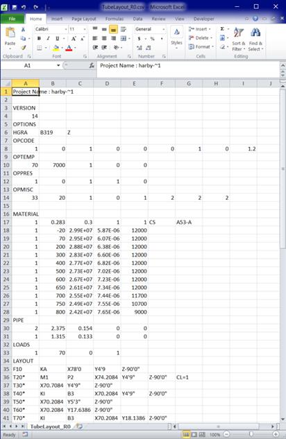
Project Name : harby-~1
VERSION
14
OPTIONS
HGRA,B319,Z
OPCODE
1,0,1,0,0,0,1,0,1.2
OPTEMP
70,7000,1,0,0,
OPPRES
1,0,1,1,0,
OPMISC
33,20,1,0,1,2,2,2,
MATERIAL
1,0.283,0.3,1,1,CS,A53-A,,
1,-20,2.99E+07,5.87E-06,12000,
1,70,2.95E+07,6.07E-06,12000,
1,200,2.88E+07,6.38E-06,12000,
1,300,2.83E+07,6.60E-06,12000,
1,400,2.77E+07,6.82E-06,12000,
1,500,2.73E+07,7.02E-06,12000,
1,600,2.67E+07,7.23E-06,12000,
1,650,2.61E+07,7.34E-06,12000,
1,700,2.55E+07,7.44E-06,11700,
1,750,2.49E+07,7.55E-06,10700,
1,800,2.42E+07,7.65E-06,9000,
PIPE
2,2.375,0.154,0,0,
1,1.315,0.133,0,0,
LOADS
1,70,0,1
LAYOUT
F10,KA,X78'0,Y4'9,Z-90'0"
T20*,M1,P2,X74.2084,Y4'9",Z-90'0",CL=1
T30*,X70.7084,Y4'9",Z-90'0"
T40*,KI,B3,X70.2084,Y4'9",Z-90'0"
T50*,X70.2084,Y5'3",Z-90'0"
T60*,X70.2084,Y17.6386,Z-90'0"
T70*,KI,B3,X70.2084,Y18.1386,Z-90'0"
T80*,X69.7084,Y18.1386,Z-90'0"
T90*,X42.7797,Y18.1386,Z-90'0"
T100*,KI,B3,X42.2797,Y18.1386,Z-90'0"
T110*,X42.2797,Y18.6386,Z-90'0"
T120*,KI,B3,X42.2797,Y19.1386,Z-90'0"
T130*,X42.2797,Y19.1386,Z-90'6"
T140*,X42.2797,Y19.1386,Z-98.3636
T150*,KI,B3,X42.2797,Y19.1386,Z-98.8636
T160*,X41.8088,Y19.3066,Z-98.8636
T170*,X12.9243,Y29.6085,Z-98.8636
T180*,KI,B3,X12.4534,Y29.7765,Z-98.8636
T190*,X12.2854,Y29.3056,Z-98.8636
T200*,X11.9777,Y28.443,Z-98.8636
T210*,KI,B3,X11.8097,Y27.9721,Z-98.8636
T220*,X11.8097,Y27.9721,Z-99.3636
T230*,X11.8097,Y27.9721,Z-101.6483
T240*,KI,B3,X11.8097,Y27.9721,Z-102.1483
T250*,X11.8097,Y28.4721,Z-102.1483
T260*,KI,B3,X11.8097,Y28.9721,Z-102.1483
T270*,X11.3097,Y28.9721,Z-102.1483
T280*,X0.8749,Y28.9721,Z-102.1483
T290*,KI,B3,X0.3749,Y28.9721,Z-102.1483
T300*,X0.3749,Y28.9721,Z-101.6483
T310*,X0.3749,Y28.9721,Z-89.6178
T320*,KI,B3,X0.3749,Y28.9721,Z-89.1178
T330*,X-0.1251,Y28.9721,Z-89.1178
T340*,X-33.4704,Y28.9721,Z-89.1178
T350*,KI,B3,X-33.9704,Y28.9721,Z-89.1178
T360*,X-33.9704,Y28.4721,Z-89.1178
T370*,X-33.9704,Y27'0",Z-89.1178
T380*,KI,B3,X-33.9704,Y26'6",Z-89.1178
T390*,X-33.9704,Y26'6",Z-89.6178
T400*,X-33.9704,Y26'6",Z-91.6072
T410*,X-33.9704,Y26'6",Z-91.9505
T420*,JD,X-33.9704,Y26'6",Z-92.2838,COD1=2.375,THK1=0.154,OD2=1.315,THK2=0.133
T430*,P1,X-33.9704,Y26'6",Z-94.3363,
T440*,KI,B1.5,X-33.9704,Y26'6",Z-94.5863
T450*,X-33.9704,Y26'9",Z-94.5863
T460*,X-33.9704,Y27'1",Z-94.5863
T470*,KI,B1.5,X-33.9704,Y27'4",Z-94.5863
T480*,X-33.9704,Y27'4",Z-94.8363
T490*,X-33.9704,Y27'4",Z-98.0863
L490,KA
Below are the key points to understand when working with this file:
1. Option: The "Option" section allows you to define the CAEPIPE Analysis Options such as Code, Temperature, Pressure, Dynamics, and Miscellaneous settings.
2. Material, Pipe and Load: These sections allow you to input materials, pipe section properties and loads for the CAEPIPE model.
3. Layout: This section contains the CAEPIPE layout data. If you observe closely the first column, you will notice an asterisk (*) that precedes the node number. This indicates that the DX, DY, DZ values provided in that line is absolute coordinates (and not relative to the previous node). This means that you can directly use coordinates extracted from your 3D piping/tubing software without any conversion to relative offsets DX, DY and DZ.
After completing the creation of CSV file, save it and change the extension from .csv to .mbf, emphasizing the fact that mbf file is the same as a CSV file. Then, import the .mbf file into CAEPIPE through the Layout Frame > Import option to generate the piping/tubing layout for analysis.