Tutorial for analysis of Fiber Reinforced Piping (FRP) using CAEPIPE
The following are the Steps for FRP Modeling and Analysis using CAEPIPE.
General
FRP piping has gained wide acceptance in many industries due to its lightweight nature, superior corrosion resistance, temperature capabilities and mechanical strength. Several manufacturers produce different types of FRP pipes and fittings and provide technical assistance to their customers on design matters through installation.
FRP piping can be modeled in CAEPIPE. CAEPIPE will then calculate deflections, element forces & moments, support loads and stresses.
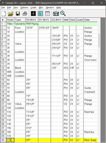
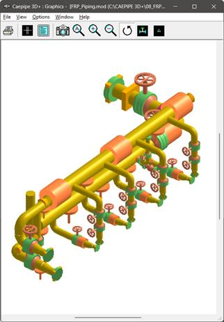
Snap shot shown below is a sample model for FRP Modeling and Analysis
Step 1:
First define FRP materials required for piping system through Layout window > Misc > Materials. In the Material List window shown on the screen, double click on an empty row to input a new material or on a material description to edit the material properties.
Step 2:
In the Material dialog shown, enter the FRP material properties as given below.
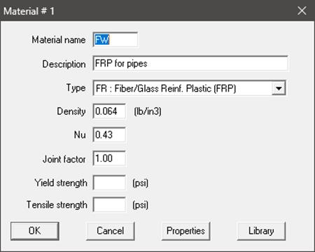
The material name can be up to five alpha-numeric characters. Enter description, density and Poisson’s ratio. You need to select “FR: Fiber Reinf. Plastic (FRP)” from the Type drop-down combo box before you click on the Properties button.
Step 3:
Click on the Properties button, you are shown the table below where you can enter temperature-dependent properties. Additionally, you can also define the Hoop, Torsional and Axial allowable stresses so that CAEPIPE can use them to compare with calculated stresses under the FRP "Sorted Stresses” results.
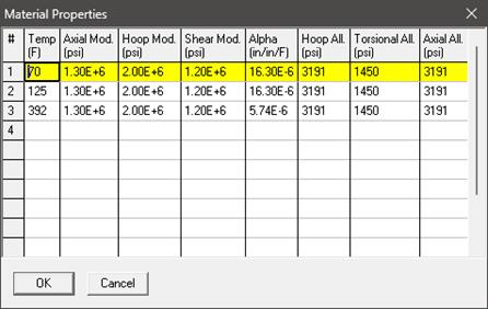
FRP Material Moduli
CAEPIPE requires three moduli for the FRP material:
Axial or Longitudinal (this is the most important one)
Hoop (used in Bourdon effect calculations). If this modulus is not available, use axial modulus.
Shear or Torsional. If this modulus is not available, use engineering judgment in specifying 1/2 of axial modulus or a similar value. Note that a high modulus will result in high stresses, and a low modulus will result in high deflections.
For FRP bends, a Flexibility factor of 1.0 is used unless you override it by specifying a Flexibility factor inside the bend dialog. Also, for FRP bends, CAEPIPE uses a default SIF of 2.3. You can override this too by specifying User-SIFs at the bend end nodes (A and B nodes).
Step 4:
After defining the FRP material properties, Section Properties and Loads required for the stress analysis, complete the stress layout. Save the model and Analyze through Layout window > File > Analyze.
Step 5:
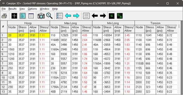
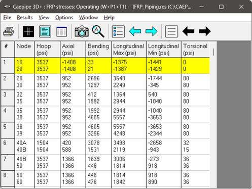
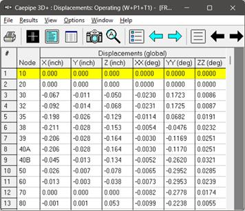
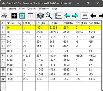
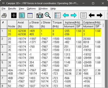
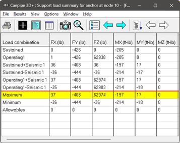
Upon successful analysis, CAEPIPE will show the calculated stresses, deflections, support loads, element forces and support load summary. Each item can be seen under the respective title in Results. FRP element stresses can be seen, sorted or unsorted.
Stiffness matrix formulated internally in CAEPIPE and the formulas used for computing different stresses are given below for quick reference.
Stiffness matrix
The stiffness matrix for a pipe is calculated using the following terms:
Axial term = L / EA
Shear term = shape factor x L / GA
Bending term = L / EI
Torsion term = L / 2GI
where L = length, A = area, I = moment of inertia, E = elastic modulus, G = shear modulus
For an isotropic material, G = E / 2(1 +  ), where = Poisson’s ratio,
For a FRP material, E = axial modulus and G is independently specified (i.e., it is not calculated using E and ).
).
The hoop modulus and FRP Poisson’s ratio are only used in Bourdon effect calculation where,
Poisson’s ratio used = FRP Poisson’s ratio input x (axial modulus / hoop modulus)
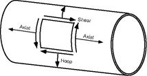
FRP Stresses
Hoop stress: 
Axial stress: 
Bending stress: 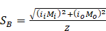
Torsional stress: 
Longitudinal maximum = Axial + Bending = SA + SB
Longitudinal Minimum = Axial – Bending = SA - SB
where
= nominal thickness x (1 – mill tolerance/100) – corrosion allowance