Tutorial for Fiber/Glass Reinforced Piping (FRP/GRP) Modeling and Analysis as per ASME NM.2 using CAEPIPE
General
FRP/GRP are being extensively used in the process, water, and chemical industries due to their high service life (about 50 years) and high resistance to corrosion. This, in turn, reduces the total cost of GRP/FRP piping incurred during such long service life compared to metallic pipes. GRP/FRP pipes are increasingly used to transfer water, oil, Fuel, Glycol, wastewater, sewer, etc. Because of this, the demand for GRP/FRP piping is continuously increasing.
Pipe Flexibility specifications/Stress Analysis Design Basis requirements used in engineering industries consider FRP/GRP piping as stress critical. So, FRP/GRP systems, irrespective of their sizes and pressure, require analysis. Hence, demand for FRP/GRP pipe stress analysis is therefore ever-increasing.
This tutorial will help to learn the steps in performing piping stress analysis of above-ground FRP/GRP piping as per ASME NM.2 using CAEPIPE.
In case the FRP/GRP piping system for analysis includes only buried piping or both above-ground and buried piping, we recommend that such FRP/GRP system is analyzed as per ISO 14692-3. The tutorial titled “FRP/GRP Modeling and Analysis as per ISO 14692-3” provides the details of such piping analysis.
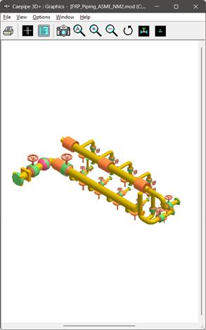
Snap shot shown below is a sample model for above-ground FRP Modeling and Analysis
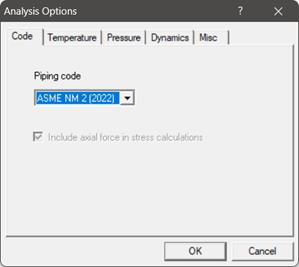
Step 1:
Select the piping code for analysis as “ASME NM.2” through Layout Window > Options > Analysis > Code as shown below and press the button “OK”.
Step 2:
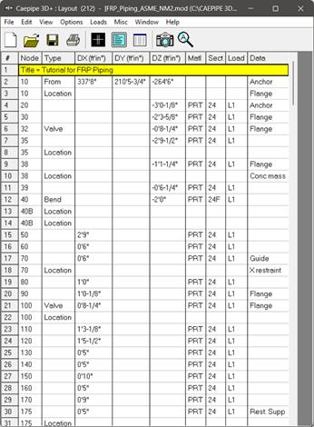
Next define FRP materials required for piping system through Layout window > Misc > Materials by obtaining their properties from the manufacturer or through the piping standard.
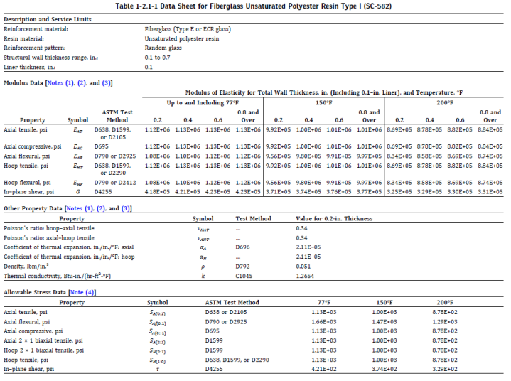
ASME NM.3.3 provides tables and data sheets for allowable stresses, mechanical and physical properties (e.g., coefficient of thermal expansion and modulus of elasticity) for Fiberglass Unsaturated Polyester Resins Type I (SC-582), Type II (SC-582) and Type III (55-deg Filament Wound; ASME NM.2, Mandatory Appendix IV).
In this tutorial, Material properties for Fiberglass Unsaturated Polyester Resins Type I (SC-582) are referred from Table 1-2.1-1 of ASME NM.3.3 corresponding to the structural wall thickness of 0.2” and entered into CAEPIPE Material properties dialog.
FRP Material Moduli
CAEPIPE requires three moduli for the FRP material:
Axial or Longitudinal (this is the most important one)
Hoop Modulus. If this modulus is not available, use axial modulus.
Shear or Torsional. If this modulus is not available, use engineering judgment in specifying 1/2 of axial modulus or a similar value. Note that a high modulus will result in high stresses, and a low modulus will result in high deflections.
In the Material List window shown on the screen, double click on an empty row to input a new material or double click on a material description to edit the material properties.
In the Material dialog shown, enter the FRP material properties as given below.
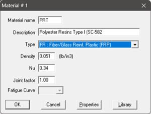
The material name can be up to five alpha-numeric characters. Enter description, density and Poisson’s ratio. You need to select “FR: Fiber Reinf. Plastic (FRP)” from the Type drop-down combo box before you click on the Properties button.
Step 3:
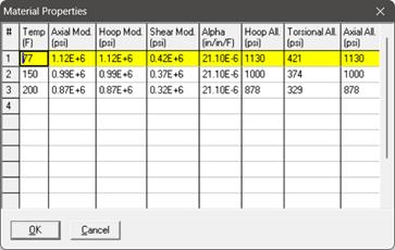
Click on the Properties button, you are shown the table below where you can enter temperature-dependent properties. Additionally, you can also define the Hoop, Torsional and Axial allowable stresses so that CAEPIPE can use them for code compliance checks as per ASME NM.2 and display them in the FRP "Sorted Stresses” results.
Step 4:
After defining the FRP material properties, Section Properties and Loads required for the stress analysis, complete the stress layout. Save the model and Analyze through Layout window > File > Analyze.
Step 5:
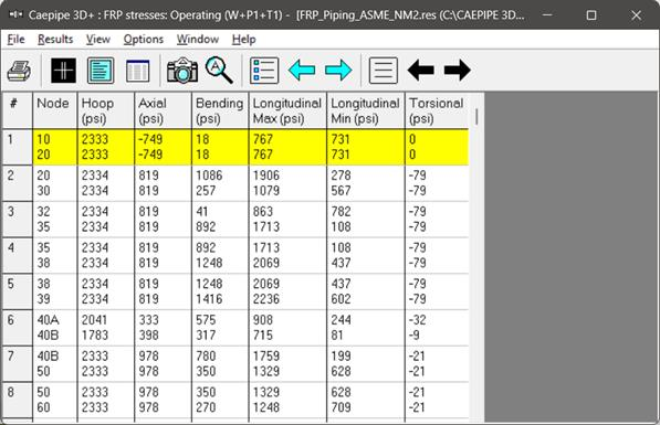
Upon successful analysis, CAEPIPE shows the code compliance as per ASME NM.2 under Sorted FRP stresses as shown below.
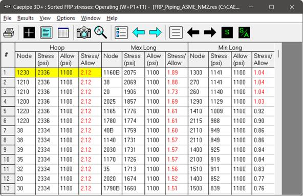
FRP stresses results of CAEPIPE display the stresses computed as per ASME NM.2 on an element-by-element basis as shown below.
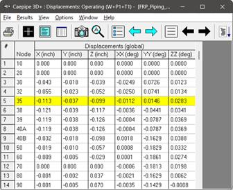
CAEPIPE will show the deflections and support loads for each load case under Deflections and Support loads results as shown below.

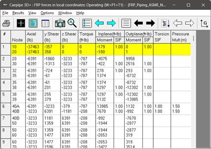
Element forces results for each load case (such as Sustained, Operating, etc.) show the Element forces and moments in local coordinate system along with Stress Intensification Factors (SIFs) and Pressure Multiplier (m) computed as per ASME NM.2 for each element as shown below.
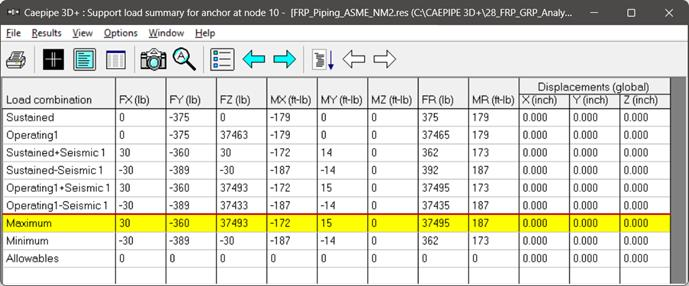
For the design of supports, Support Load Summary of CAEPIPE will show the loads on each support for all load cases selected for analysis as given below.
Stiffness matrix formulated internally in CAEPIPE is given below for quick reference.
Stiffness matrix
The stiffness matrix for a pipe is calculated using the following terms:
Axial term = L / EA
Shear term = shape factor x L / GA
Bending term = L / EI
Torsion term = L / 2GI
where L = length, A = area, I = moment of inertia, E = elastic modulus, G = shear modulus
For an isotropic material, G = E / 2(1 +  ), where = Poisson’s ratio,
For a FRP material, E = axial modulus and G is independently specified (i.e., it is not calculated using E and ).
).
The hoop modulus and FRP Poisson’s ratio are only used in Bourdon effect calculation where,
Poisson’s ratio used = FRP Poisson’s ratio input x (axial modulus / hoop modulus)
Note:
Refer to Section titled “ASME NM.2” in CAEPIPE Code Compliance Manual of CAEPIPE for details on how CAEPIPE computes the Flexibility Factors, Stress Intensification Factors and Code Stresses as per ASME NM.2.