Tutorial on Cryogenic Piping using CAEPIPE
Analysis of Cryogenic Piping as per ASME B31.5 Code:
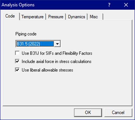
The snap shot below shows the sample layout of a cryogenic piping system. The system experiences an Operating Temperature during its operation as -130 deg. C with its Design Temperature as -195 deg. C. The installation temperature is 20 deg. C. For this cryogenic piping, the analysis code is selected as ASME B31.5 as this code is used for Refrigeration Piping analysis that includes sub-zero temperatures.
Step 1:
Select the Analysis code as ASME B31.5 (2022) through Layout Window > Options > Analysis as shown below.
Step 2:
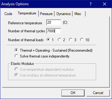
As the piping layout involves one (1) operating temperature, “Number of Thermal Loads” needs to be set as “1”. This can be done through Layout Window > Analysis > Temperature as shown below. In addition, the installation temperature (same as “Reference temperature”) can be input as shown below.
Note:
As per para. 519.4.5(a) of ASME B31.5 (2022), bending and torsional stresses shall be computed using the as-installed modulus of elasticity, i.e., Ec at installation temperature (same as “Reference temperature”). Hence, "Use modulus at reference temperature" is set as "default" and is disabled for user to modify.
Step 3:
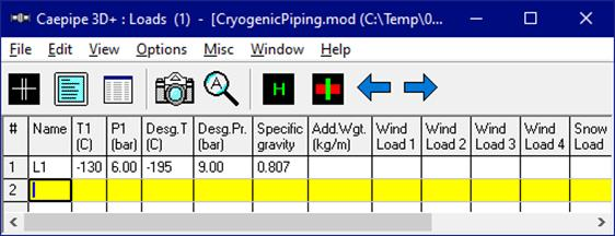
Enter the Operating Temperature (T1), Operating Pressure (P1), Design Temperature (Desg. T) and Design Pressure (Desg. Pr) of the piping layout through “Layout Window > Misc > Loads” as shown below. Specific Gravity of the Liquid Nitrogen with respect to water is entered as 0.807 to include the content weight in the analysis. From the link https://demaco-cryogenics.com/blog/liquid-nitrogen-density-and-weight/, the density of the Liquid Nitrogen is taken as 807 kg/m3 at -196 deg. C.
Note:
Design Temperature entered will be used to determine the allowable stress for material, which is in turn used to compute the Allowable Pressure as per the piping code selected (B31.5 in this case).
The Allowable Pressure so computed as per the piping code selected is then compared against the Design Pressure entered above and reported in the Code Compliance results.
In addition, when Design (W+PD+TD) load case is selected for Analysis, CAEPIPE will compute and show results for Displacements, Element Forces & Moments, Support Loads and Support Load Summary. This Design load case is NOT included in Stress Calculations, Rotating Equipment Qualifications and Flange Equivalent Pressure Calculations, as many of the piping and equipment codes do not require the qualification to be carried out at Design condition.
Step 4:
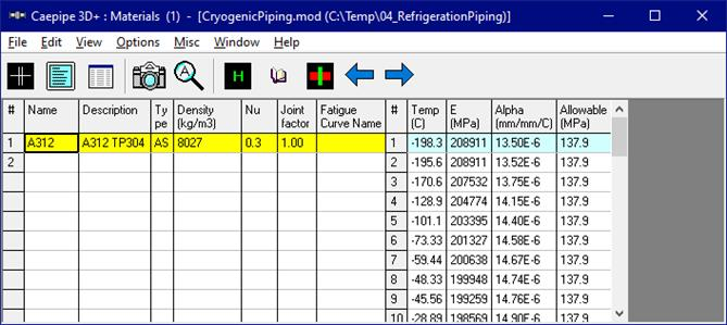
Material properties corresponding to the cryogenic temperature considered for this analysis are not available in ASME B31.5 (2022) code. On the other hand, ASME B31.3 (2024) code includes several materials for sub-zero temperatures. For example, for this analysis, we have chosen a material with name ASTM A312 TP304 that contains mechanical properties corresponding to the sub-zero temperatures up to -198 deg. C from the ASME B31.3 (2024) Material library. This material library supplied with CAEPIPE software is available in the CAEPIPE installation folder\Material_Library. The material from this library can be selected through “Layout Window > Misc > Materials > File > Library…> Library > Material_Library > B313-2024.mat”.
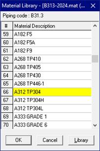
From the dialog box shown, select the Material as A312 TP304 and press the button “OK”.
Step 5:
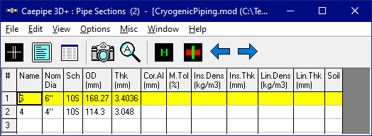
Define the section properties through “Layout Window > Misc > Sections”.
Step 6:
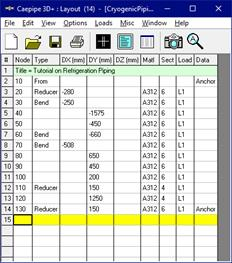
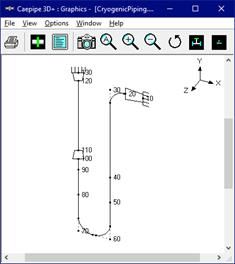
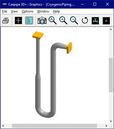
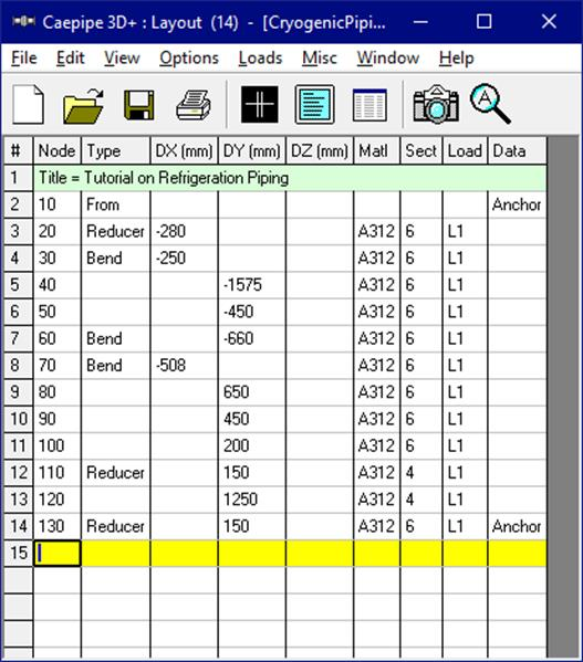
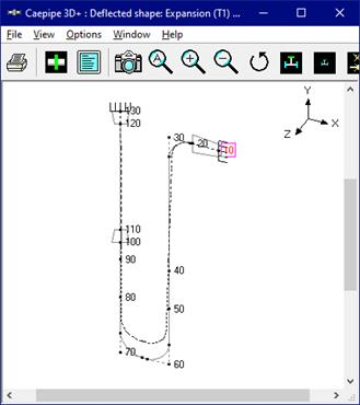
Generate the piping layout as shown below.
Step 7:
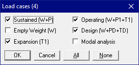
After creating the stress model, turn ON load cases through “Layout Window > Loads > Load cases as follows: Expansion (T1) {which is the same as the range (T1 – Tref)}.
Step 8:
Save the model and perform analysis through Layout window > File > Analyze.
In order to understand the loads and load combinations used for analysis, review the CAEPIPE results file for Sorted Stress, Code Compliance, Displacements, Support Loads (loads acting on the supports by the piping for each load case), Element Forces & Moments (local/global forces and moments on each element for each load case) and Support Load Summary (listing support loads at a particular support for all relevant load cases and load combinations).
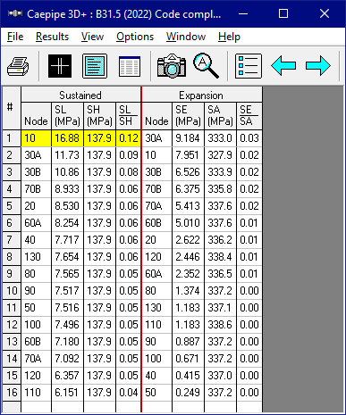
As stated above, Sorted Stresses in CAEPIPE lists the maximum of Expansion stresses for all thermal range cases at each node (only T1 – Tref in this case). On the other hand, for Sustained case, it always uses the maximum pressure among the input pressures (only P1 in this case) while computing Sustained Stress at each node.
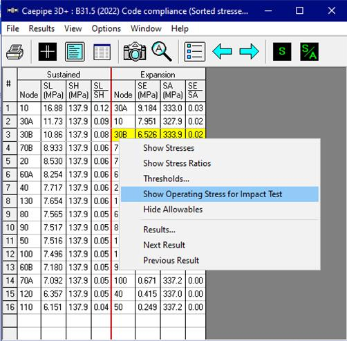
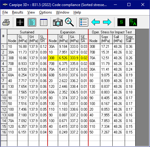
Operating Stress for Impact Test can be seen by selecting the option “Show Operating Stress for Impact Test” through Mouse Right click.
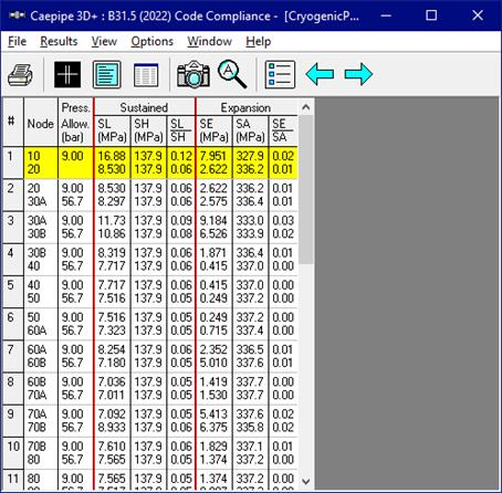
Similarly, Code Compliance report lists the Stresses element-wise following the same procedure as done for Sorted Stresses.
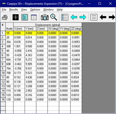
From the Displacement results for Expansion (T1), it is observed that the Displacements are +ve in Global Y direction confirming that the piping is shrinking due to temperature decrease under cryogenic conditions.
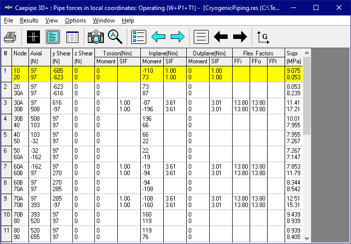
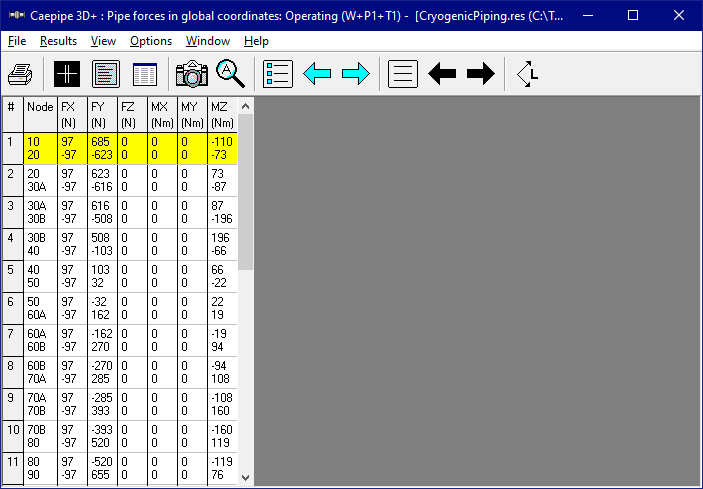
Element Forces & Moments (local and global forces and moments) on each element for Operating load case are shown below.
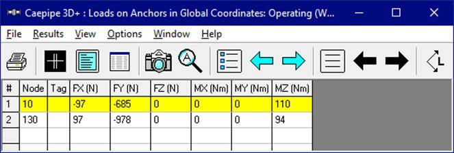
Support Loads on all supports by the piping for Operating Load case 1 are shown below.
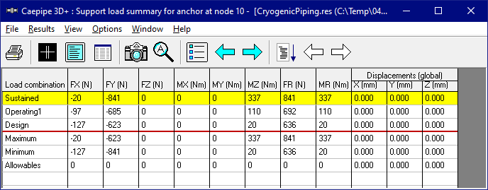
Support Load Summary [listing loads on a particular support (at Anchor Node 10) by the piping] for all relevant load cases is shown below.