Tutorial on Flange Qualification using CAEPIPE
This document explains the procedure on performing Flange Qualification using CAEPIPE.
General
Flange joints are essential components in all pressurized systems; they are also one of the most complex. Many factors are involved in determining the successful design and operation of a bolted flange joint service, namely, the interaction between the bolting, flange, and gasket as well as important non-linear variables such as friction and gasket properties. The Pressure Vessel and Piping Codes were developed with safety in mind; they provide a method for sizing the flange and bolts to be structurally adequate for the specified design conditions.
The Flange Qualification module implemented in CAEPIPE addresses the design rules contained in the ASME Section VIII, Division 1, Appendix 2 on bolted flange connections with gaskets.
These design rules will help you to obtain better insight into a flange joint's tendency to leak, beyond the insight gathered from CAEPIPE’s results as per NC3658.1 of ASME Section III Class 2, 1992 or later editions under Results > Flange Report. You can examine the flange and bolt stresses arising from the bolt tightening loads required for a leakage-free joint.
Step 1:
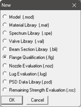
Flange Qualification module calculates flange and bolt stresses which are separate from a piping model (.mod) file. This module can be accessed/created through Main Frame > File > Open/New command.
When you first create a new flange qualification file, it comes populated with default values for a sample flange.
As this module accepts axial load and bending moment at a flange as input among many others, you will need to first create in CAEPIPE your piping model that includes flanges (which you need to validate) and generate a Flange Report. Such a report will contain the information you can now use in the Flange Qualification module to calculate flange and bolt stresses.
Step 2:
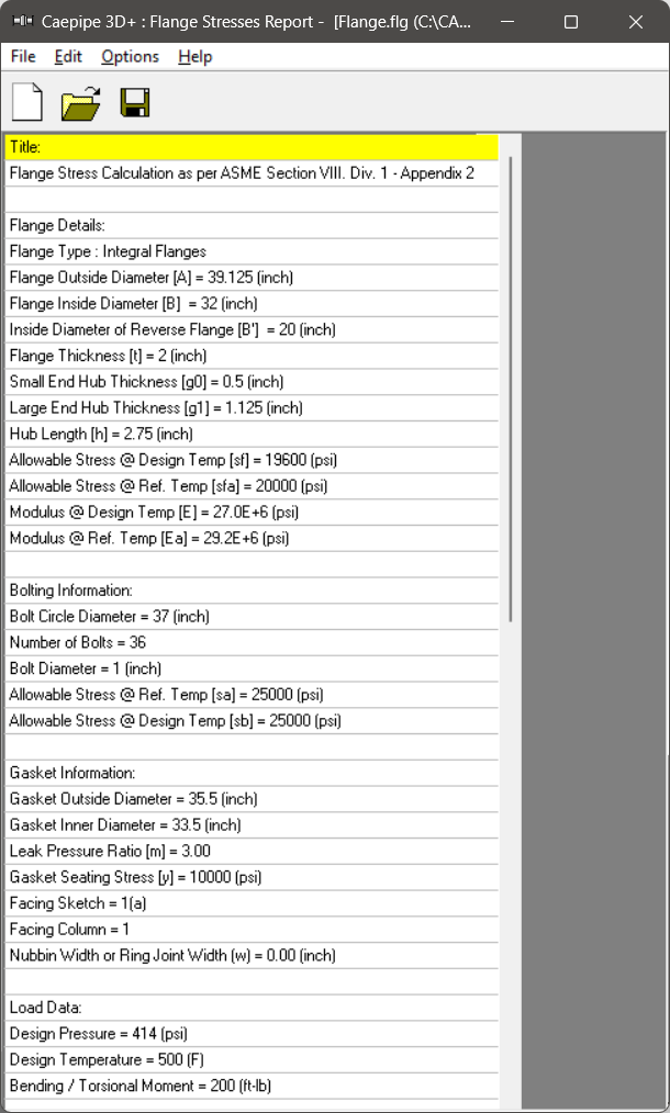
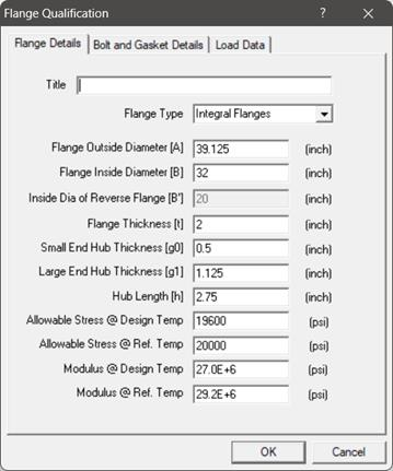
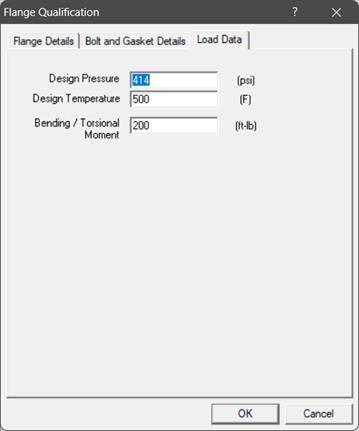
Double-clicking anywhere in the window shown (or select the option Edit menu > Edit (Ctrl+E)) opens a dialog with input fields (already populated with default values) which you can now edit. You will need to enter all of your flange data in this dialog. Legends of the different parameters you see here are explained in detail towards the end of this document.
Step 3:
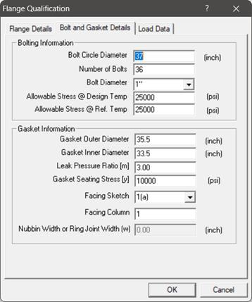
Required flange input information is organized into three Property tabs – Flange Details, Bolt and Gasket Details, and Load Data, the last of which accepts data from a piping model’s Flange Report.
Step 4:
Once all the data values are input, save the model (Flange Qualification filenames will have a .flg extension). Now, select File menu > Analyze to calculate flange stresses, which will be shown right below the input information.
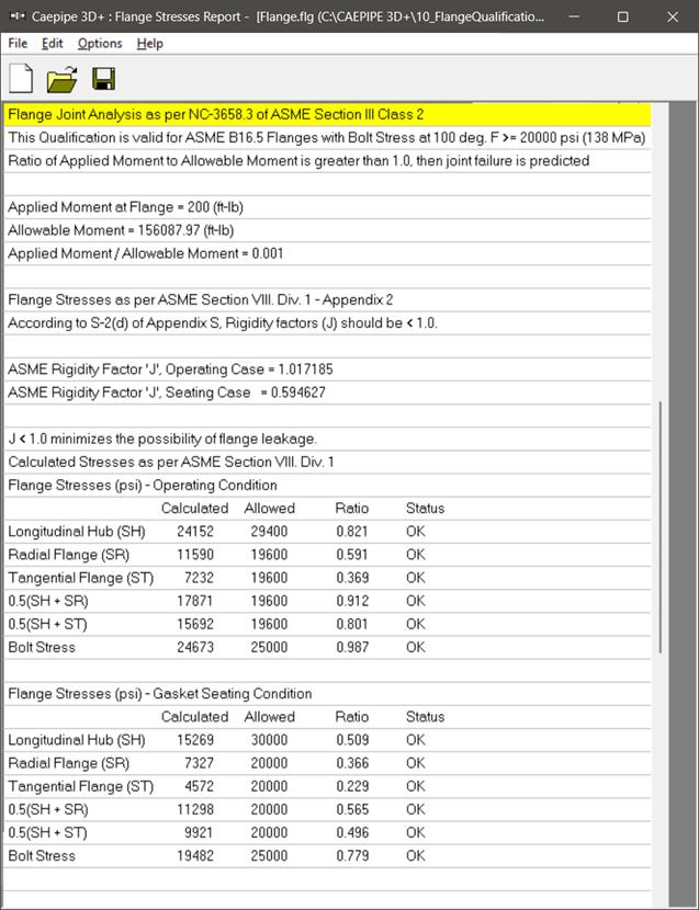
There are three main sections in the results shown:
Flange Allowable Moment as per NC3658.3 of ASME Section III Class 2,
Flange Stresses for Operating Case as per Appendix 2 of ASME Section VIII Division 1, and
Flange Stresses for Gasket Seating Case as per Appendix 2 of ASME Section VIII Division 1.
Step 5:
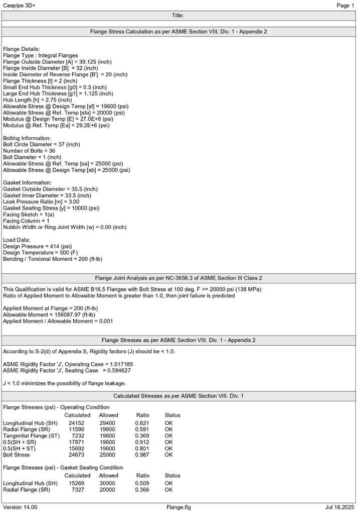
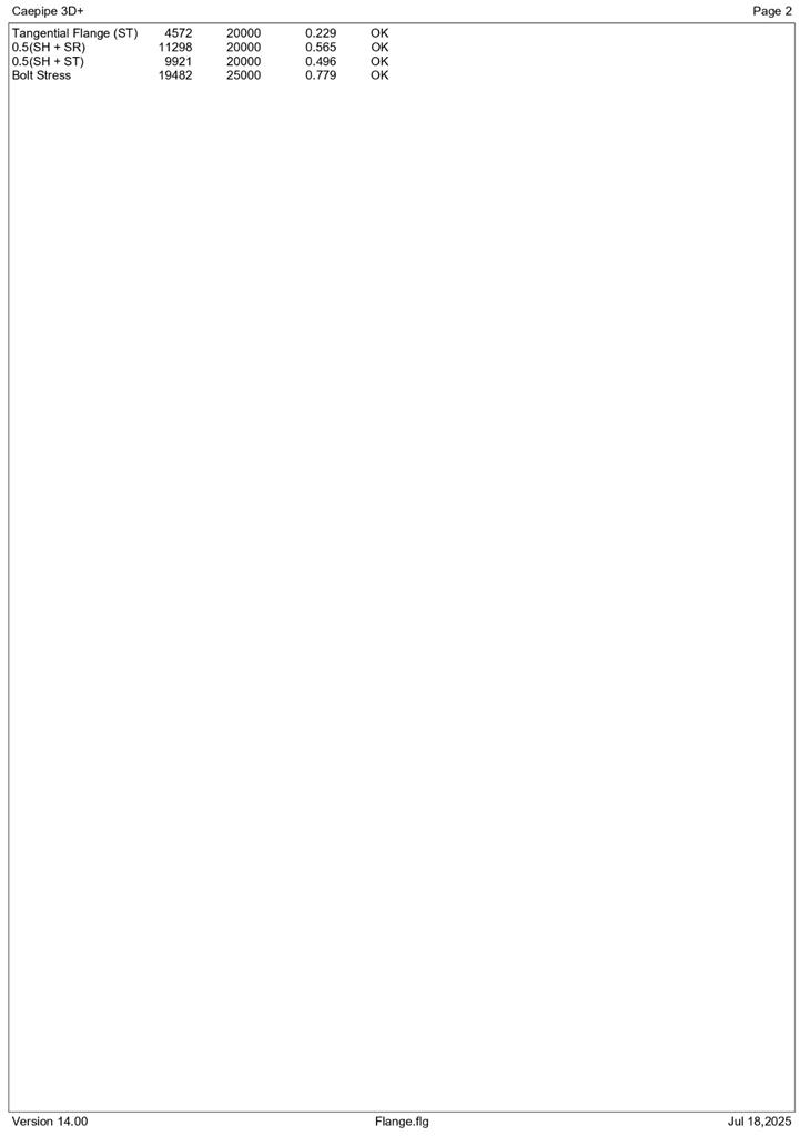
You can print a Flange Report by using the Print command. You can also preview the report by clicking the Preview button on the print dialog.
Flange Qualification as per ASME Section VIII, Division 1, Appendix 2 (2013)
Notations
The symbols described below are used in the formulas for the design of flanges
stress, required for the operating conditions
=  for operating condition
=  for gasket seating condition
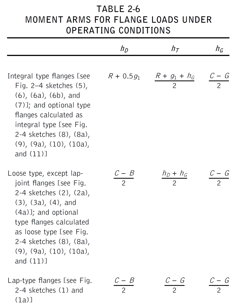
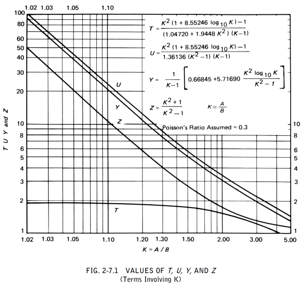
Calculation of Flange Stresses
The stresses in the flange shall be determined for both the operating conditions and gasket seating condition, in accordance with the following formulas:
(1) Integral type flanges
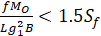
Longitudinal hub stress  =
= 
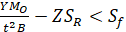
Radial flange stress  =
= 
Tangential flange stress  =
= 
Combined stress
(2) Loose type flanges with hubs
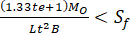
Longitudinal hub stress =
Radial flange stress =
Tangential flange stress =
Combined stress
where,
(3) Loose type flanges without hubs
Longitudinal hub stress = 0
Radial flange stress = 0
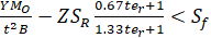
Tangential flange stress 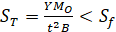
Combined stress
where,
(4) Optional type flanges (calculated as loose flanges without hubs)
Longitudinal hub stress = 0
Radial flange stress = 0
Tangential flange stress
Combined stress
where,


(5) Reverse type flanges
Longitudinal hub stress = 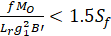
Radial flange stress = 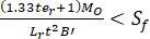
Tangential flange stress  =
=
Combined stress
where,
Problem 1:
(Example from “Taylor Forge & Pipe Works, 1961”)
Flange Details:
Flange Type: Loose Flanges with Hubs
Flange Outside Diameter [A] = 40.375 (inch)
Flange Inside Diameter [B] = 33.25 (inch)
Inside Diameter of Reverse Flange [B] = 20 (inch)
Flange Thickness [t] = 2.125 (inch)
Small End Hub Thickness [g0] = 0.875 (inch)
Large End Hub Thickness [g1] = 1.125 (inch)
Hub Length [h] = 2.5 (inch)
Allowable Stress @ Design Temp [sf] = 17500 (psi)
Allowable Stress @ Ref. Temp [sfa] = 17500 (psi)
Modulus @ Design Temp [E] = 2.7E+7 (psi)
Modulus @ Ref. Temp [Ea] = 2.92E+7 (psi)
Bolting Information:
Bolt Circle Diameter = 38.25 (inch)
Number of Bolts = 44
Bolt Diameter = 1 (inch)
Allowable Stress @ Ref. Temp [sa] = 20000 (psi)
Allowable Stress @ Design Temp [sb] = 20000 (psi)
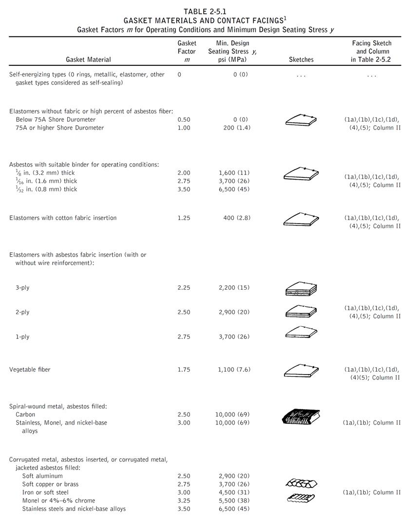
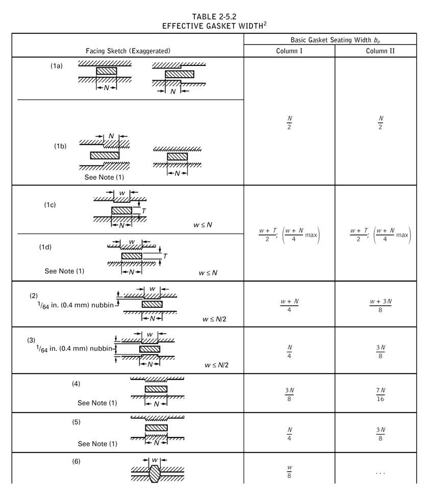
Gasket Information:
Gasket Outside Diameter = 35.75 (inch)
Gasket Inner Diameter = 34.25 (inch)
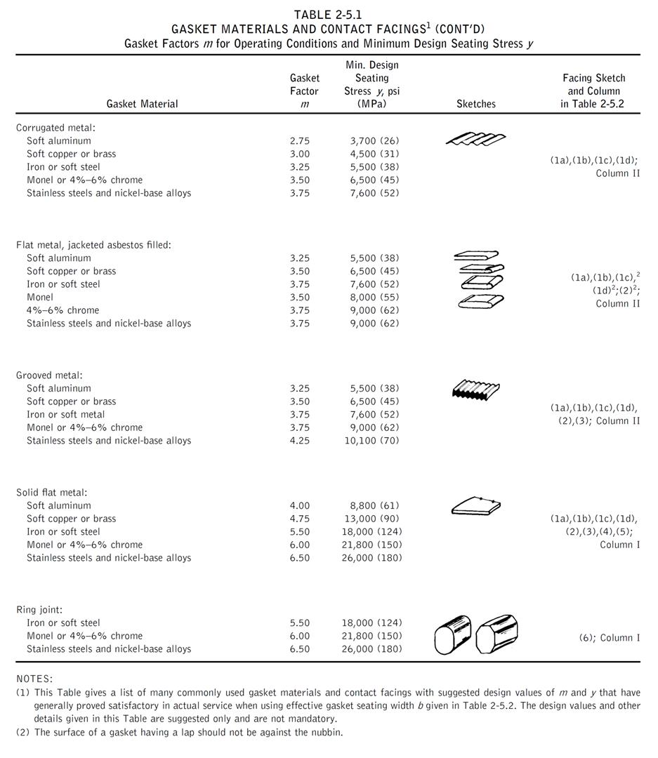
Leak Pressure Ratio [m] = 2.75
Gasket Seating Stress [y] = 3700 (psi)
Facing Sketch = 1
Facing Column = 1
Load Data:
Design Pressure = 400 (psi)
Design Temperature = 500 (F)
Bending Moment = 200 (ft-lb)
Comparison of Results:
|
Flange Stresses
|
Text Book Results
(psi)
|
CAEPIPE
(psi)
|
Other Software
(psi)
|
|
Operating condition
|
|
|
|
|
Longitudinal Hub (SH)
|
20800
|
21153
|
21214
|
|
Radial Flange (SR)
|
11100
|
11110
|
11155
|
|
Tangential Flange (ST)
|
13800
|
13826
|
13797
|
|
0.5(SH + SR)
|
15950
|
16132
|
16185
|
|
0.5(SH + ST)
|
17300
|
17489
|
17506
|
|
Gasket Seating Condition
|
|
|
|
|
Longitudinal Hub (SH)
|
14400
|
14623
|
15095
|
|
Radial Flange (SR)
|
7660
|
7681
|
7938
|
|
Tangential Flange (ST)
|
9500
|
9558
|
9818
|
|
0.5(SH + SR)
|
11030
|
11152
|
11517
|
|
0.5(SH + ST)
|
11950
|
12091
|
12457
|
Problem 2:
(Example 10.5 on page 209 Chapter 10 on “CASTI Guidebook to ASME Section VIII Div.1 – Pressure Vessels – Third Edition”)
Flange Details:
Flange Type: Reverse Flanges
Flange Outside Diameter [A] = 49 (inch)
Flange Inside Diameter [B] = 48.25 (inch)
Inside Diameter of Reverse Flange [B] = 20.25 (inch)
Flange Thickness [t] = 5.25 (inch)
Small End Hub Thickness [g0] = 0.375 (inch)
Large End Hub Thickness [g1] = 1.375 (inch)
Hub Length [h] = 6 (inch)
Allowable Stress @ Design Temp [sf] = 12000 (psi)
Allowable Stress @ Ref. Temp [sfa] = 20000 (psi)
Modulus @ Design Temp [E] = 2.7E+7 (psi)
Modulus @ Ref. Temp [Ea] = 2.92E+7 (psi)
Bolting Information:
Bolt Circle Diameter = 44 (inch)
Number of Bolts = 32
Bolt Diameter = 1.25 (inch)
Allowable Stress @ Ref. Temp [sa] = 25000 (psi)
Allowable Stress @ Design Temp [sb] = 21000 (psi)
Gasket Information:
Gasket Outside Diameter = 24 (inch)
Gasket Inner Diameter = 22 (inch)
Leak Pressure Ratio [m] = 2.50
Gasket Seating Stress [y] = 10000 (psi)
Facing Sketch = 1
Facing Column = 1
Load Data:
Design Pressure = 150 (psi)
Design Temperature = 800 (F)
Bending Moment = 200 (ft-lb)
Comparison of Results:
|
Flange Stresses
|
Text Book Results
(psi)
|
CAEPIPE
(psi)
|
Other Software
(psi)
|
|
Operating condition
|
|
|
|
|
Longitudinal Hub (SH)
|
2060
|
2257
|
2055
|
|
Radial Flange (SR)
|
280
|
307
|
280
|
|
Tangential Flange (ST)
|
1340
|
1314
|
1336
|
|
0.5(SH + SR)
|
1170
|
1282
|
1168
|
|
0.5(SH + ST)
|
1700
|
1785
|
1695
|
|
Gasket Seating Condition
|
|
|
|
|
Longitudinal Hub (SH)
|
9220
|
10082
|
9220
|
|
Radial Flange (SR)
|
1260
|
1372
|
1257
|
|
Tangential Flange (ST)
|
6000
|
7004
|
5997
|
|
0.5(SH + SR)
|
5240
|
5727
|
5239
|
|
0.5(SH + ST)
|
7610
|
8543
|
8703
|
Problem 3:
(Example from KEDKEP CONSULTING, INC. dated May 27, 2008)
Flange Details:
Flange Type: Loose Flanges without Hubs / Optional Flanges
Flange Outside Diameter [A] = 38.4 (inch)
Flange Inside Diameter [B] = 32 (inch)
Inside Diameter of Reverse Flange [B'] = 32 (inch)
Flange Thickness [t] = 4 (inch)
Small End Hub Thickness [g0] = 0.001 (inch)
Large End Hub Thickness [g1] = 0.001 (inch)
Hub Length [h] = 0.001 (inch)
Allowable Stress @ Design Temp [sf] = 20000 (psi)
Allowable Stress @ Ref. Temp [sfa] = 20000 (psi)
Modulus @ Design Temp [E] = 2.7E+7 (psi)
Modulus @ Ref. Temp [Ea] = 2.92E+7 (psi)
Bolting Information:
Bolt Circle Diameter = 36 (inch)
Number of Bolts = 28
Bolt Diameter = 1 (inch)
Allowable Stress @ Ref. Temp [sa] = 25000 (psi)
Allowable Stress @ Design Temp [sb] = 25000 (psi)
Gasket Information:
Gasket Outside Diameter = 32.75 (inch)
Gasket Inner Diameter = 32 (inch)
Leak Pressure Ratio [m] = 0.50
Gasket Seating Stress [y] = 0 (psi)
Facing Sketch = 2
Facing Column = 2
Load Data:
Design Pressure = 300 (psi)
Design Temperature = 295 (F)
Bending Moment = 200 (ft-lb)
Comparison of Results:
|
Flange Stresses
|
Text Book Results
(psi)
|
CAEPIPE
(psi)
|
Other Software
(psi)
|
|
Operating Condition
| |||
|
Longitudinal Hub (SH)
|
0
|
0
|
3
|
|
Radial Flange (SR)
|
0
|
0
|
0
|
|
Tangential Flange (ST)
|
10577
|
10569
|
10618
|
|
0.5(SH + SR)
|
0
|
0
|
1.5
|
|
0.5(SH + ST)
|
0
|
0
|
5310.5
|
|
Bolt Stress
|
16378
|
16371
|
16445
|
|
Gasket Seating Condition
| |||
|
Longitudinal Hub (SH)
|
0
|
0
|
3
|
|
Radial Flange (SR)
|
0
|
0
|
0
|
|
Tangential Flange (ST)
|
12147
|
11987
|
12166
|
|
0.5(SH + SR)
|
0
|
0
|
1.5
|
|
0.5(SH + ST)
|
0
|
0
|
6085
|
|
Bolt Stress
|
0
|
0
|
124
|