Tutorial on Qualification of Nozzles to Equipment using CAEPIPE
The following are the steps for qualifying nozzles welded to Spherical/Cylindrical Vessels such as pressure vessels, tanks etc. using CAEPIPE.
General
Often pipe stress engineers face difficulties on the following while analyzing any piping system.
· Obtaining or computing the allowable loads at nozzles attached to Spherical / Cylindrical Vessels and Torispherical Heads, and
· Keeping the external loads imposed by piping on equipment nozzles within allowable limits.
The above difficulties can be overcome in CAEPIPE by
· Using the module “Nozzle Evaluation” for calculating allowable loads at nozzles welded to Spherical / Cylindrical Vessels and Torispherical Heads.
· Incorporating the local shell flexibility at the nozzle-to-shell junctions while carrying out piping stress analysis.
This tutorial provides stepwise procedure for
1. Computing allowable loads on nozzles to Spherical / Cylindrical Vessels and Torispherical Heads,
2. Modeling the nozzle-to-shell junction as “Nozzle” to incorporate local shell flexibility, and
3. Inputting the nozzle allowable loads thus computed into CAEPIPE stress system as “User Defined Allowable” for equipment qualification.
Step 1:
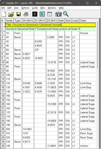
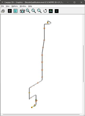
From the attached model (snap shot shown above), assume the following.
Node 10 is the intersection of a Nozzle to a Spherical Shell / Torispherical Head of a vessel.
Node 420 is the intersection of a side Nozzle to a Cylindrical Vessel.
Step 2:
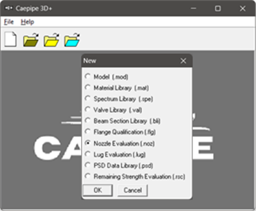 From the equipment drawings provided by the manufacturer for Spherical Shell / Torispherical Head, the following properties are entered into “Nozzle Evaluation” module of CAEPIPE through Main Frame > New > Nozzle Evaluation.
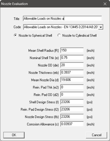
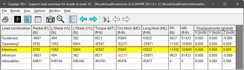
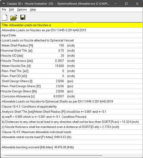
After entering the details, press the button “OK”, save the model and perform the analysis through File > Analyze. This computes the allowable radial nozzle load as well as the allowable bending moment on nozzle welded to Spherical Shell. See snap shot below for details.
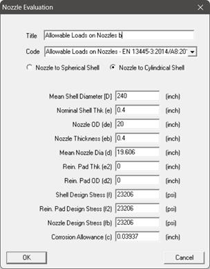
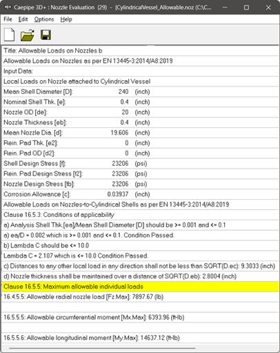
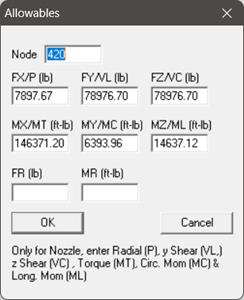
In a similar fashion, from the equipment drawings provided by the manufacturer for Cylindrical Vessel, the following properties are entered into “Nozzle Evaluation” module of CAEPIPE through Main Frame > New > Nozzle Allowable Loads.
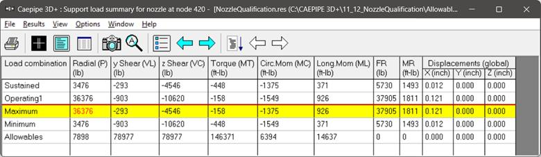
After entering the details, press the button “OK”, save the model and perform the analysis through File > Analyze. This computes the allowable radial nozzle load as well as the allowable bending moments in the circumferential and longitudinal directions as shown below.
For both types of nozzles, the allowable loads in the two shear directions and in the torsional direction can be assumed to be very much larger than the corresponding allowable for the radial load and bending moment directions, as the shell is very stiff in those directions.
Step 3:
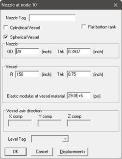
Enter the data type of Node 10 as “Nozzle” and input the properties as shown below.
Step 4:
Similarly, enter the data type of Node 420 as “Nozzle” and input the properties as shown below.
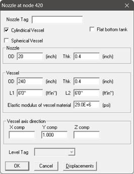
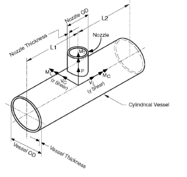
From the snap shot shown above, Lengths L1 and L2 on either side of the nozzle, which are the distances from the nozzle center line to the nearest location on vessel where the "ovalization deformation" of the vessel is stopped such as at a stiffener on the inner or outer surface of the vessel, or at the center of a saddle support to the vessel or at the junction to the torispherical enclosure (also called the head) or at a tube sheet inside the vessel etc.
Step 5:
Input the allowable loads on the two Nozzles computed in Step 2 above in CAEPIPE through Layout window > Misc > User Allowables.

The allowable loads for the two shear and torsional directions are assumed to be ten (10) times the corresponding allowables for the radial and bending directions.
Step 6:
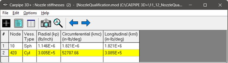
Save the model and perform the analysis through Layout window > File > Analyze. CAEPIPE will include in the pipe stress analysis the local shell stiffnesses internally computed at both nozzle-to-spherical and nozzle-to-cylindrical shell junctions. These local shell stiffnesses can be seen in CAEPIPE through Layout window > View > List > Nozzle stiffnesses.
Step 7:
Upon successful analysis, from the “Support load summary” results, it is to be noted that the CAEPIPE has included the “User Allowables” entered in the stress system for equipment qualification as shown below.