Tutorial on Tall Vertical Pipe Riser using CAEPIPE
General
Tall vertical pipe risers in multi-storey buildings present unique modeling and design challenges. The presence of fluid generates significant forces at supports, while thermal expansion or contraction (from steam, hot water, or chilled water) causes the riser length to vary, leading to additional stresses. If not properly accounted for, these effects can cause:
· Excessive load transfer into the building structure
· High localized stresses in the pipe wall
· Failure of supports or restraints
CAEPIPE, a stand-alone stress analysis software included in CAEPIPE 3D+ can model tall vertical risers effectively. However, special care is required when handling fluid weight under Sustained, Operating, and Occasional load cases.
This tutorial explains the modeling approach in the following sections:
Section 1 – Modeling a riser with resting supports and uniformly distributed fluid weight.
Section 2 – Correcting the model to account for the full fluid column weight at the bottom of the riser.
Section 3 – Modeling the riser under Occasional (e.g., seismic) load case with lateral restraints.
Section 1: Modeling and analysis of tall vertical pipe riser with distributed fluid weight and weight supports at regular intervals
Step 1.1:
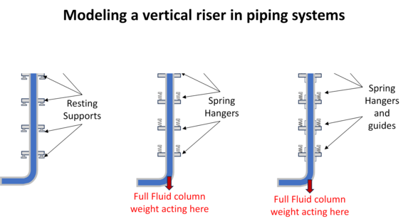
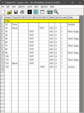
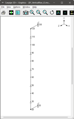
Consider the following layout of a 100’ tall vertical pipe riser in a 10-storey building. The vertical riser is supported by resting supports at every 20’ as shown below. This means that the tall vertical pipe riser is supported by resting supports at alternate floors (assuming average floor height as 10’).
By default, CAEPIPE distributes the fluid weight of each element equally to its two end nodes. Thus, the riser is modeled as if the fluid weight is uniformly applied across its length.
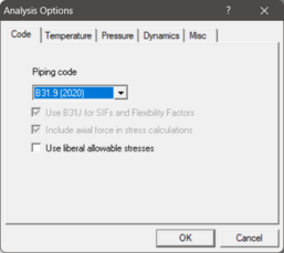
The analysis code is selected as ASME B31.9 (2020) via Options > Analysis > Code.
Step 1.2:
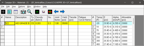
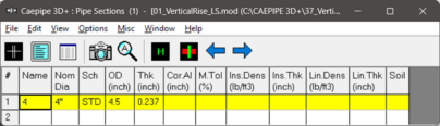
Material properties, Pipe Sections and Loads used in this model can be seen through Materials, Sections and Loads options respectively from Layout window > Misc.
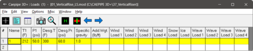
From the Loads dialog, you can observe that the Operating Temperature and Pressure are input as 212 deg.F and 50 psi respectively. The Operating fluid is assumed to be water.
Note: In this model, the pressure is conservatively taken as 50 psi, corresponding to the maximum pressure at the bottom of the fluid column.
Step 1.3:
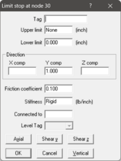
At nodes 30, 50, 70, 90 and 110, resting supports (vertical limit stops) are modelled as shown.
Step 1.4:
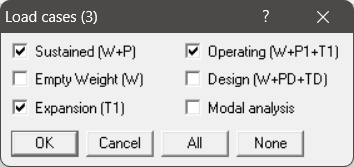
Select the required Load cases through Loads > Load Cases. Save the model with a name (say 01_VerticalRise_LS.mod) and perform the analysis through Layout window > File > Analyze.
Step 1.5:
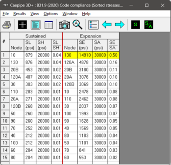
After successful analysis, review the CAEPIPE results file. The figure below shows the sorted stresses. It can be observed that all stress ratios for Sustained and Expansion load cases are well below 1.0, thereby meeting the ASME B31.9 (2020) Code Compliance.
Step 1.6:
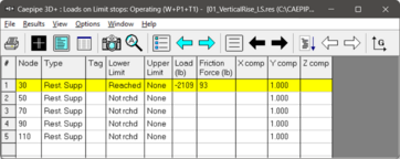
The support loads for the Operating (W+P+T) load case in Local Coordinate System for all the Limit Stops are shown below. It can be observed that for the Operating load case, the Lower Limit is shown as “Reached” only for the Limit Stop at Node 30. This means that the tall vertical pipe riser is lifting up at all other Limit Stops due to thermal expansion. In other words, all Limit Stops other than that at Node 30 are not carrying any weight during operation.
Hence, the only way that the weight of the pipe and fluid can be carried by all five (5) support points along the tall vertical riser without interfering with the thermal expansion is by replacing the Limit Stops with Variable Spring Hangers.
Step 1.7:
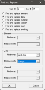
In the existing layout, replace all the Resting Supports (Vertical Limit Stops) with Spring Hangers. In CAEPIPE, this can be easily done by finding and replacing the data type “Limit Stop” with “Hangers” through Edit > “Find and Replace” command as shown in the figure below.
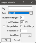
Step 1.8:
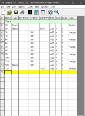
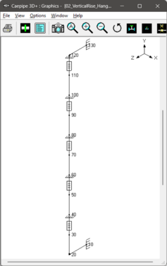
The figure below shows the modified layout wherein the Limit Stops are replaced with Variable Spring Hangers.
Step 1.9:
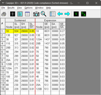
Save the model (File > Save) with a different name (say, 02_VerticalRise_Hangers.mod) and run the analysis (File > Analyze). From the sorted stresses results, it is observed that the stress ratios for both Sustained and Expansion load cases are well below 1.0, thereby meeting the Code Compliance as per ASME B31.9 (2020).
Step 1.10:
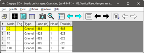
The Hanger loads for Operating load case shows non-zero load values at all hangers, thereby confirming that the weight of the tall vertical pipe riser along with its content weight are carried by all hangers without interfering with the thermal expansion of the piping.
NOTE: In the above stress layout, it was assumed that the fluid weight is acting uniformly across each pipe element in tall vertical pipe riser. But, in reality, the entire weight of the riser fluid column acts vertically downwards at the bottom of the vertical riser. In order to model the content weight accurately, follow the procedure given in Section 2 below.
Section 2: Analysis of tall vertical pipe riser by applying the entire fluid column weight at the bottom of the vertical riser
We can achieve the above by applying upward forces at the nodes of each vertical pipe element to cancel out the default internally computed fluid weight distribution. In doing so, the element’s fluid weight is excluded from the sustained load case. The total weight of the entire fluid column is then applied as a single downward concentrated force at the bottom-most node (the bend center node) of the riser. To implement this, follow the steps below:
Step 2.1:
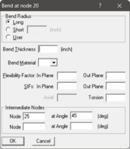
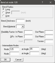
Create intermediate nodes 25 and 125 at 45 degrees by editing the Bend at nodes 20 and 120, respectively as shown below.
Step 2.2:
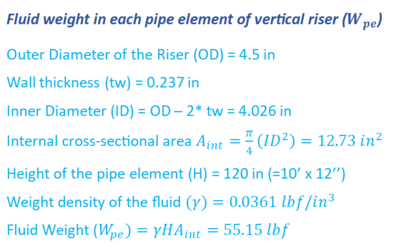
Calculate the fluid weight for each pipe element in the vertical riser. Because all elements in this layout have the same length, each element will have the same fluid weight. Manually compute the fluid content weight per element as follows.
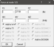
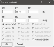
As explained, by default, CAEPIPE distributes each element’s fluid weight equally between its two end nodes. To cancel this, place force cards at both nodes of every element, applying an upward force (0.5Wpe) at each node (where Wpe is the element’s fluid weight). Repeating this for all elements results in:
· Internal nodes: net upward force of Wpe
· External nodes (bend nodes 25 and 125): Upward force of (0.5Wpe) each
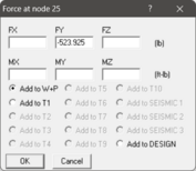
However, for the bottom most node (Node 25), we must also account for the total fluid column weight. Therefore, the force card at this node should apply a downward force equal to the total fluid column weight minus (0.5Wpe)
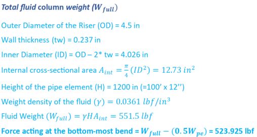
The force card details for the top node, internal nodes, and bottom node are shown below.
The final layout is shown below.
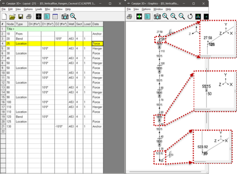
Step 2.3:
Save the model (File > Save) with a different name (say, 03_VerticalRise_Hangers_Cw.mod) and run the analysis (File > Analyze).
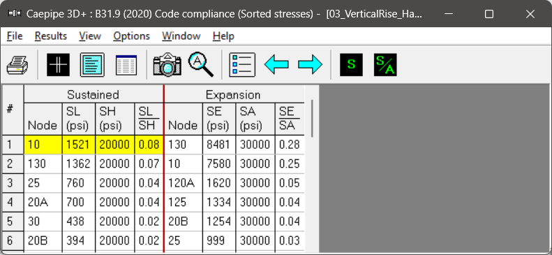
Step 2.4:
From the Sorted Stresses results, it is observed that all stress ratios for Sustained and Expansion load cases are well below 1.0 as before.
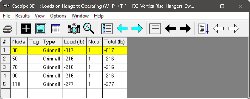
Step 2.5:
It can be observed that the Hanger load at Node 30 shows much greater value as this node is closer to the bend node 25, where the concentrated fluid weight is applied.
Note: Hangers can support the vertical weight of the pipe but do not provide restraint against lateral movement during a seismic event. To maintain stability of the tall vertical riser under such conditions, lateral supports must be introduced. Section 3 describes how to model these lateral supports for the Occasional load case.
Section 3: Modeling and analysis of tall vertical pipe riser for occasional load case
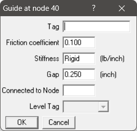
Step 3.1:
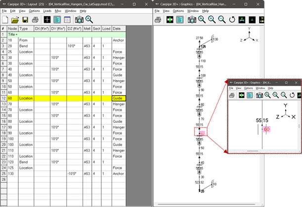
Lateral supports can be added along the vertical riser to restrict horizontal movement under Occasional load cases (e.g., seismic loads) while still permitting free vertical thermal expansion. This is achieved by inserting Guides with clearance gaps at alternate nodes (Nodes 40, 60, 80, and 100), as illustrated below.
Step 3.2:
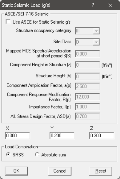
Turn on Static Seismic load case through Loads > Static Seismic 1… , and input the details.
Step 3.3:
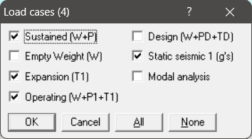
The modified layout with the selected load cases is shown in the figures below.
Step 3.4:
Save the model with a different name (say, 04_VerticalRise_Hangers_Cw_LatSupp.mod) and run the analysis through File > Analyze.
Step 3.5:
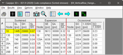
From the sorted stresses results, it is observed that all stress ratios for Sustained, Expansion and Occasional load cases are well below 1.0, thereby meeting ASME B31.9 (2020) Code Compliance.
Step 3.6:
The support loads at Hangers and Guides under Sustained, Operating and Seismic load cases are shown below.
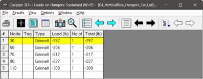
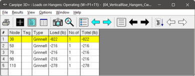
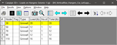
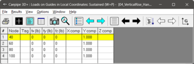

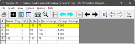
It can be seen that the Spring Hanger at Node 30 carries the largest share of the load, as it is closest to the bottom bend where the entire fluid column weight is applied under Sustained and Operating load cases. The Guides also register non-zero lateral loads (in the Local Coordinate System) during the Seismic load case, confirming that they engage once the gaps close and effectively restrain lateral movement.
Conclusions:
Sections 1 through 3 demonstrate how to model a tall vertical pipe riser in CAEPIPE. As shown, accurate modeling requires both the correct treatment of fluid weight and careful selection and placement of supports. For a conservative analysis, follow these practices:
· Use Hangers instead of Resting Supports to carry the combined weight of the pipe and fluid, since the riser will typically lift off resting supports under Operating load cases.
· Account for fluid weight correctly: In Sustained and Operating load cases, the entire fluid column weight acts at the bottom of the riser. Because CAEPIPE, by default, distributes fluid weight across each element’s end nodes, this effect must be corrected by applying opposing forces at the nodes of vertical pipe elements and a concentrated load at the bottom of riser.
· Provide lateral supports (Guides) to restrain horizontal movement under Occasional load cases such as seismic, while still allowing vertical thermal expansion.