Fatigue Evaluation
Simplified Fatigue Evaluation
Starting CAEPIPE Version 13.00, a new feature is added to perform Simplified Fatigue Evaluation. This evaluation can be turned ON or OFF through Loads > Simplified Fatigue.
CAEPIPE will compute the equivalent number of full displacement cycles (N) expected during the service life of the piping system as per the Piping Code selected for analysis. When done, it will use this computed full displacement cycles (N) to determine the Stress Range Reduction Factor (f or U) in computing the Expansion Allowable Stress as per the Piping Code selected. Refer to the Section titled “Simplified Fatigue” in CAEPIPE Code Compliance Manual for details on the equations used to compute N for various Piping Codes.
Detailed Fatigue Evaluation
Detailed Fatigue Evaluation can be performed in CAEPIPE starting Version 13.00.
Miner’s Rule, also known as the Cumulative Damage Theory, is the method implemented in CAEPIPE to estimate the fatigue life of piping subjected to cyclic loadings. This rule helps in predicting the failure based on the accumulated damage to the piping from such cyclic loadings. For further details on Evaluation method, refer to the Section titled “Detailed Fatigue Evaluation” in CAEPIPE Code Compliance Manual.
Detailed Fatigue Evaluation can be turned ON or OFF through Loads > Detailed Fatigue. Refer to the Sections titled “Detailed Fatigue Evaluation”, “Fatigue Curves” and “Fatigue Cycles” in CAEPIPE User’s Manual for details on inputting the data required for Detailed Fatigue Evaluation.
Example Calculation
Assume a piping system experiences the following cyclic loading conditions:
· Expansion (T1): Alternating Stress amplitude of 15000 psi, with 5000 cycles.
· Expansion (T2): Alternating Stress amplitude of 30000 psi, with 2000 cycles.
The stress amplitudes listed above are one-half of the stress range values (=SE/2.0) at a particular Node for Expansion (T1) and Expansion (T2) cases respectively.
From the sample S-N curve given below, 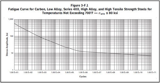
· At Alternating Stress 15000 psi: N1 (Number of cycles to failure) = 1E+6 cycles.
· At Alternating Stress 30000 psi: N2 (Number of cycles to failure) = 1E+4 cycles.
Calculate damage:
· Damage at 15000 psi: n1/N1 = 5000/1E+6 = 0.005
· Damage at 30000 psi: n2/N2 = 2000/1E+4 = 0.200
· Total Cumulative Damage: D = 0.005 + 0.2 = 0.205
Since D < 1.0, the component meets the Fatigue requirement for the given cyclic loading conditions, though it will have consumed 20.5% of its total allowable fatigue life.
Actual Number of Cycles to be Input for Simplified and Detailed Fatigue Analysis:
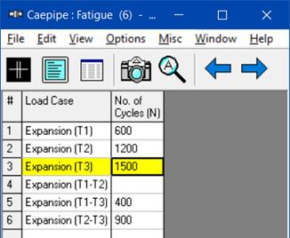
In CAEPIPE, the actual number of cycles associated with each selected expansion load case can be entered as shown below. When Simplified or Detailed Fatigue Analysis is enabled, CAEPIPE utilizes this table (containing the actual number of cycles for the selected load cases) to perform both Simplified and Detailed Fatigue Analysis. Please note, as stated above, when any of the load cases is not to be included in the Fatigue Evaluation, then leave the ‘Number of Cycles (N)’ field for that load case BLANK as shown below.
When Simplified Fatigue Analysis is turned ON, CAEPIPE uses the above table for calculating the “equivalent reference displacement stress range cycles (N)”, which then is used to compute the stress range reduction factor (‘f’ or ‘U’) as detailed in the section titled ‘Simplified Fatigue Evaluation’ in the CAEPIPE Code Compliance Manual.
Similarly, when the Detailed Fatigue Analysis is turned ON, CAEPIPE uses the above table to compute the “Cumulative Damage (D)” as outlined in the section titled ‘Detailed Fatigue Evaluation’ in the CAEPIPE Code Compliance Manual.
For better clarity, refer to the example given below for inputting the Fatigue Cycle table:
Consider a piping system that operates at three different temperature levels, each with a corresponding number of cycles over its service life and with the reference temperature of  .
.
20 cycles of 
10 cycles of 
100 cycles of
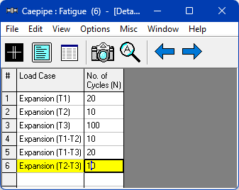
With reference to the above temperature ranges, the number of cycles that can be entered in CAEPIPE for each load case are as follows.
· For Expansion  , the number of cycles=20
· For Expansion  , the number of cycles=10
· For Expansion  , the number of cycles=100
· For Expansion  , the number of cycles = Min(
  = Min(20,10) = 10
· For Expansion  , the number of cycles = Min(
  = Min(20,100) = 20
· For Expansion  , the number of cycles = Min(
  = Min(10,100) = 10
Accordingly, the Fatigue Cycle table in CAEPIPE is to be input as shown below.
The above approach to input the number of cycles is conservative as the sum of the Number of Cycles input is greater than the sum of actual number of cycles (i.e., [170 = 20+10+100+10+20+10] > [130 = 20+10+100]). There may be alternate ways to input the number of cycles, such as “combining” or "lumping" the ranges of variations to produce the maximum effect as stated in Clause NB-3553 ‘Fatigue Usage’ of ASME Section III, Subsection NB (2021).
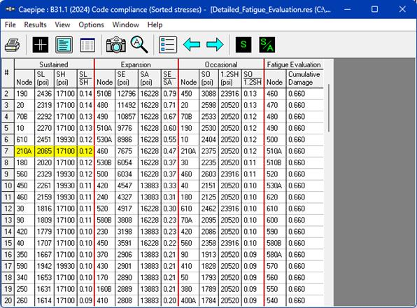
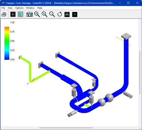
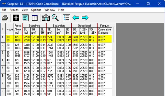
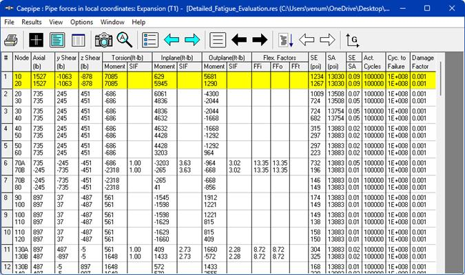
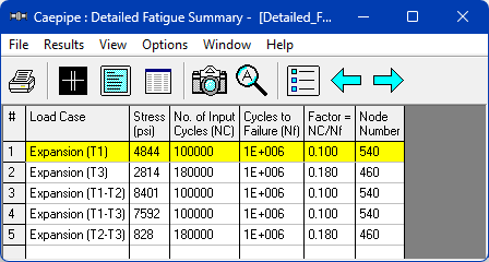
Detailed Fatigue Evaluation results can be reviewed through the Sorted Stresses, Code Compliance, Element forces and Fatigue Summary options as shown below.