Limit Stop
In CAEPIPE, a limit stop is capable of modeling several types of physical supports including a guide, an anchor, a resting support, a two-way rigid restraint and a rod hanger. Using a combination of upper and lower gaps (limits), friction coefficient, support stiffness and a direction for its axis, you can model the above mentioned physical support types.
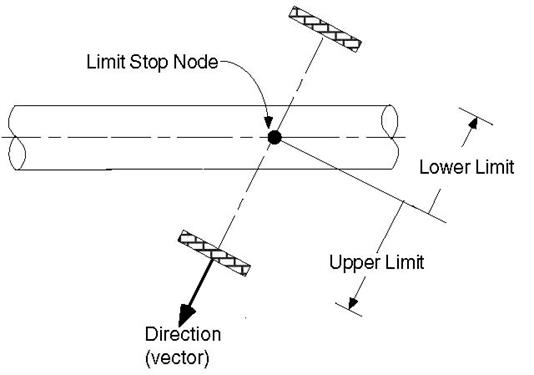
A limit stop prevents a node from moving beyond a certain distance (called a gap or a limit) in a certain direction. The node can move freely within the gap. After the gap closes, a limit stop acts as a rigid or flexible restraint (depending on your input for stiffness) resisting further movement of the node in the specified direction. If friction is specified, after the limit is reached, the friction force will oppose movement in the plane normal to the limit stop direction.
A limit stop is input by typing “l(L)” in the Data column or selecting “Limit Stop” from the Data Types dialog.
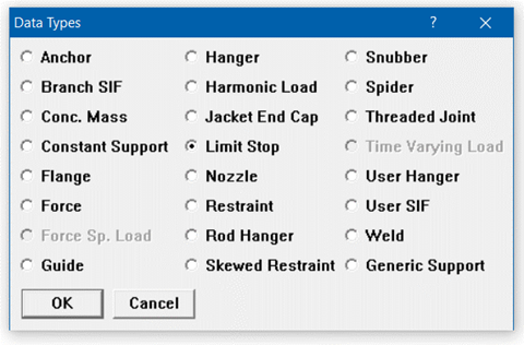
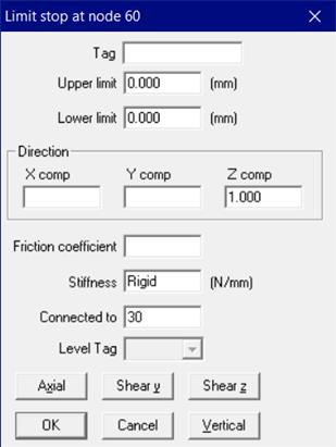
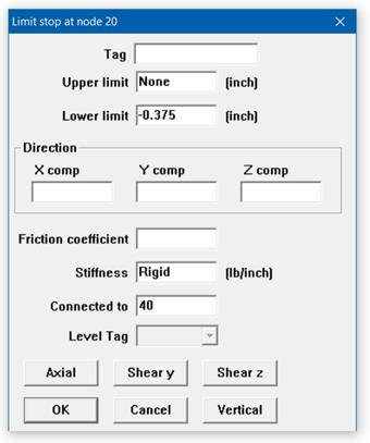
The Limit Stop dialog is shown.
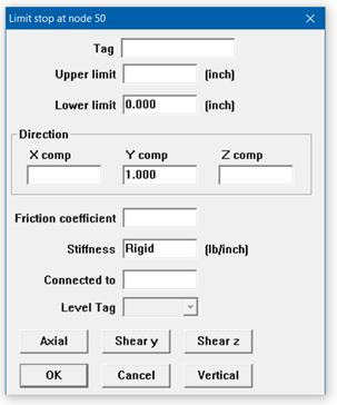
Limits
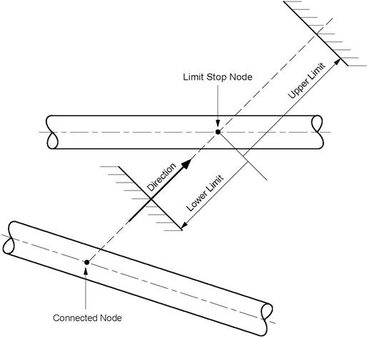
Also called gaps, these limits, upper and lower, are the gaps present on either side of the node. The gap in front of the node in the direction of the vector is called the upper limit, and the gap to the rear of the node is called the lower limit. The gap is measured from the undeflected position of the node.
Typically, the upper limit is positive and the lower limit negative. In some situations, it is possible to have a positive lower limit or a negative upper limit, which is the same as forcefully displacing the node in that direction by the gap specified.
The algebraic value of the upper limit must be greater than the lower limit. For example, upper limit = –0.125”, lower limit= –0.25”, or upper limit = 0.25”, lower limit = –0.25”.
If a particular limit does not exist (that is, a node can move freely on that side of the node), then that limit should be left blank (as in the case of a resting support, the upper limit should be blank assuming Y-vertical and Y comp = 1, as in the figure shown).
If there is no gap at all, then the corresponding limit should be explicitly input as zero. When zero is entered, the limit stop acts as a one-way restraint in that direction.
Direction
The direction in which the limit stop is oriented must be specified in terms of its global X, Y and Z components. Or use one of the preset buttons to orient the limit stop axis (see above image):
1. Vertical: To set the limit stop axis in the (global) vertical direction
2. Axial: To set the limit stop axis along the local-x direction (pipe axis)
3. Shear y: To set the limit stop axis in the local-y direction of pipe
4. Shear z: To set the limit stop axis in the local-z direction of pipe
If a Limit Stop direction is parallel to Global Vertical Axis with Lower Limit as 0.0 and Upper Limit as NONE, then CAEPIPE will show the Description in the Layout and List Windows for Limit Stop as “Rest. Supp” (Resting Support).
Similarly, when a Limit Stop is parallel to the local shear y axis of pipe (when Global Z is vertical) or is parallel to the local shear z axis of pipe (when Global Y is vertical) with both upper and lower limits input with numerals, then CAEPIPE will show the Description in the Layout and List Windows for Limit Stop as “Lateral Supp”.
If you have connected the limit stop node to another node in the same piping model, then unless the connected node is coincident with the limit stop node, the limit stop direction must not be input. Direction of the limit stop is calculated from the locations of the connected node and the limit stop node, and its direction is oriented from the connected node to the limit stop node.
On the other hand, when you input both limit stop direction as well as the connected node, then CAEPIPE will apply the stiffness input at limit stop dialog in the same direction as the limit stop direction specified, while coupling the limit stop node to the connected node.
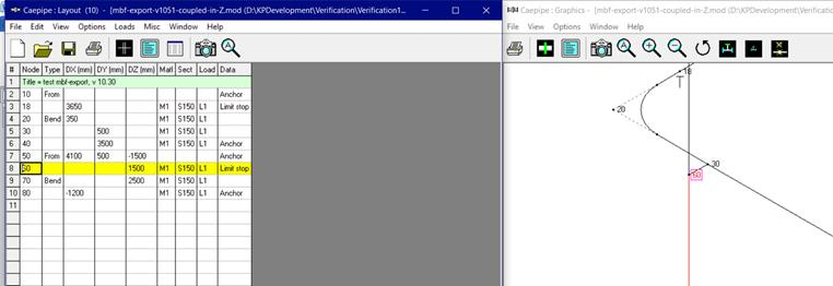
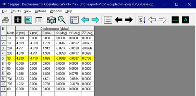
For example, in the sample model shown below, the limit stop defined at node 60 is connected to node 30 in the horizontal plane with direction of limit stop input as +Z (0.00, 0.00, 1.00). In this case, “Rigid” stiffness of this limit stop is applied in the limit stop direction (in this case +Z direction). At the same time, since node 30 and node 60 are connected, the displacements in +Z direction at both node 30 and node 60 will be identical, while the other 2-translational and 3-rotational deformations at the node 30 and node 60 can be different (see the snap shot below with highlight).
Friction coefficient
If friction coefficient is specified, a friction force will oppose the movement in the plane normal to the limit stop direction when the gap is closed. This friction force is displayed in results under Limit stop support loads.
If you had several limit stops with friction coefficients specified, and you wanted to change all of those friction coefficients to the same value, use the Change command under the Edit menu.
The default is set to Rigid stiffness. Other values may be input by estimating the stiffness of the support. (e.g., for a rod, stiffness = AE/L).
where
Connected to Node
You can connect a limit stop node to another node in the same piping model. During gap and friction calculations, the relative displacements of the limit stop node are calculated with respect to the connected node. If you connect the limit stop node to an external fixed point (Ground point), leave the “Connected to Node” blank. See “Direction” above for information about how the direction is calculated depending on whether the connected node is coincident or not with the limit stop node.
Solution procedure
Limit stops require a nonlinear iterative solution. If you specify a friction coefficient, the following procedure is used for convergence: If the lower or upper limit is reached, the corresponding reaction force is calculated. The maximum friction force is the product of friction coefficient and the reaction force. The solution converges when the displacement varies by less than 1% between successive iterations.
Limit stops are included in dynamic analysis. The status of the limit stops arrived at upon completion of all iterative calculations for the first operating case (W+P1+T1) is used during dynamic analysis. If either the lower limit or the upper limit is reached at the end of iterations for the first operating case, then that limit stop is treated as a rigid two-way restraint in the direction of the limit stop during dynamic analysis. If both limits are not reached, then that limit stop is ignored during dynamic analysis.
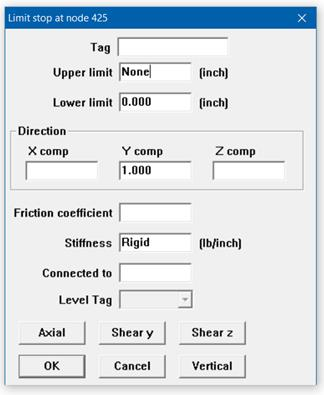
Example 1: Vertical 1-way restraint
Assume that you have a vertical 1-way support with the following data: Upper limit = None, Lower limit = 0, Friction coefficient = 0.3, Direction vector of the limit stop is vertical along +Y axis.
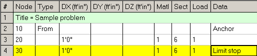
Model the pipe up to the Limit stop node 30. At node 30, type “l(L)” in the Data column. The limit stop dialog will be shown.
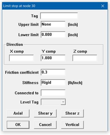
In the limit stop dialog, press “Vertical” button. The data is automatically entered [0.000 for Lower limit, None for Upper limit (blank), 1.000 for Y comp (vertical)]. Enter 0.3 for friction coefficient (this acts in the X-Z plane which is perpendicular to the direction of the limit stop).
Example 2: Pipe Slide/Shoe Assembly
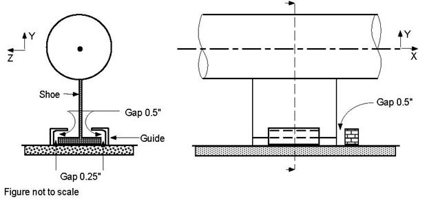
The assembly is modeled using three limit stops, one in each direction.
u When you start a new model file, node 10 and an Anchor are automatically input, press Enter to move cursor to next empty row.
u Press Tab in the Node column which puts the node number 20 automatically. Type 5’ for DX, enter material, section and load names, press Enter.
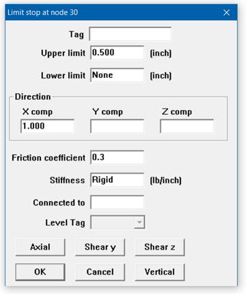
u Press Tab in the Node column which puts the node number 30 automatically. Type 5’ for DX, Tab to Data column and type “l(L)” to open limit stop dialog. Input line stop with gap (0.5”) along X axis (Notice that this is a one-way restraint; there is only one stop block along +X). Type Upper limit 0.5”, leave lower limit blank, Direction as (X comp = 1, Y comp = 0, Z comp = 0), Friction coefficient=0.3, press Enter.
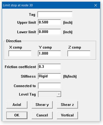
u Create a limit stop in the Y direction. Type 30 for Node, press Tab to move to Type field, type “L” for Location, choose Limit stop from the Data Types dialog, in the Limit stop dialog, type Upper limit = 0.5”, Lower limit = 0.0, Direction (X comp =0, Y comp = 1, Z comp = 0), Friction coefficient=0.3, press Enter.
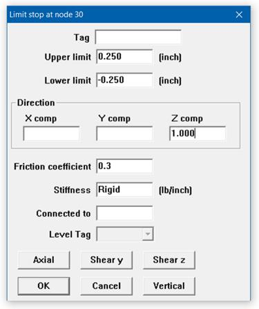
u Create a limit stop in the Z direction. Type 30 for Node, press Tab to move to Type field, type “L” for Location, choose Limit stop from the Data Types dialog, in the Limit stop dialog, type Upper limit = 0.25”, Lower limit = –0.25”, Direction (X comp =0, Y comp = 0, Z comp = 1), Friction coefficient =0.3, press Enter.
The Layout window is shown below.
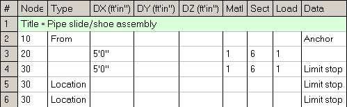
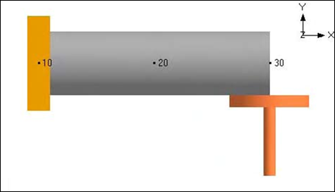
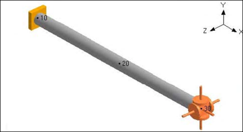
The Graphics window is shown below.
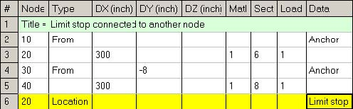
Example 3: Limit Stop Connected to Another Node
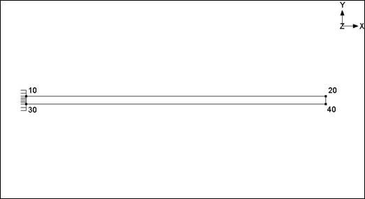
As shown in the figure below, two 300” long cantilever pipes are connected with an 8” separation between center lines.
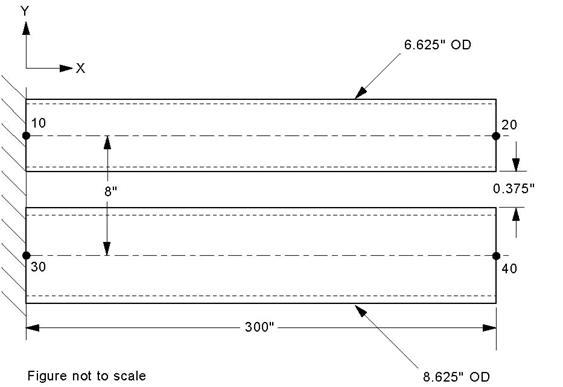
The gap between the bottom of the top pipe and the top of the bottom pipe is
8” – (6.625” + 8.625”) / 2 = 0.375”.
If pipes were free to deflect downward due to deadweight, the top pipe will deflect 1.908” and the bottom pipe will deflect 1.116” at the free ends. The relative deflection between them will be 1.908” – 1.116” = 0.792”. This however is not possible because when the relative deflection exceeds 0.375” the pipes will touch. This situation can be modeled using a limit stop connecting the free ends of the pipes. In this case the top pipe deflects 1.608”, i.e., less than the 1.908” free deflection because it is resisted by the bottom pipe. The bottom pipe deflects 1.233”, i.e., more than the 1.116” free deflection because additional load is imposed on it by the top pipe when they touch. The difference between the deflections is 1.608 – 1.233 = 0.375” as expected.
u When you start a new model file, node 10 and an Anchor are automatically input, press Enter to move cursor to next empty row.
u Press Tab in the Node column which puts the node number 20 automatically. Type 300” for DX, enter material, 6” section and load names, press Enter.
u For the bottom pipe, start with node 30 of Type “From” at DY = –8” and make it an anchor. On the next row enter node 40 with DX = 300” and 8” section. Press Enter to go to the next row.
u Enter the limit stop at node 20. Type 20 for Node, press Tab to move to Type field, type “L” for Location, choose Limit stop from the Data Types dialog, in the Limit stop dialog, leave the Upper limit blank and input Lower limit = -0.375”. Input the Connecting Node as 40. Since this limit stop connects two nodes, the direction should be left blank. The direction is implicitly from node 40 to node 20.
Alternatively, the limit stop could be specified at node 40 connected to node 20. The direction now would be from node 20 to 40. The limits would then be Lower limit = None and Upper limit = 0.375” since the direction is now reversed compared to the previous case. Both these cases will give identical results.
The Layout window is shown below.
The Graphics is shown below.