Miter Bend
Miter bends are typically used when space limitations do not allow the use of regular bends (elbows), or when a miter is more economical to use than a regular bend. Miters are not fittings. They are fabricated from pipe, to requirements. “The use of miters to make changes in direction is practically restricted to low-pressure lines, 10-inch and larger if the pressure drop is unimportant...” (Sherwood 1980).
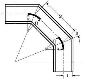
See figure below for Miter bend parameters.
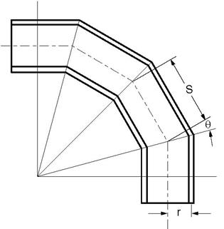
In this figure, r = mean radius of pipe
S = miter spacing at center line
Before modeling a miter bend, you should determine whether it is closely or widely spaced.
Closely Spaced Miter
A miter bend is closely spaced when 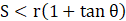 .
.
A closely spaced miter bend is input as a single miter bend element.
The Bend Radius (R) is calculated as: R = 0.5 S cot q.
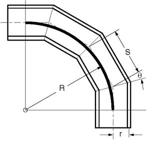
Widely Spaced Miter
A miter bend is widely spaced when 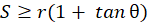 .
.
A widely spaced miter bend is modeled with as many miter bend elements as there are miter cuts.
The Bend Radius (R) is calculated as: 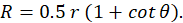
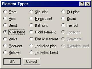
A miter bend is input by typing “m” in the Type column or selecting “Miter bend” from the Element types dialog.
The Miter bend dialog is shown.
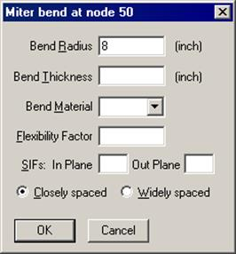
Bend Radius
The bend radius (R) depends on the type of miter (Closely or Widely spaced). It is calculated as explained previously and input in this field.
Bend Thickness
Input the wall thickness of the miter bend if it is different from that of the adjoining pipe thicknesses. The Bend Thickness, if specified, applies only to the curved portion(s) of the equivalent bend(s) of the miter bend.
Bend Material
If the material of the miter bend is different from that of the adjoining pipe, select the Bend Material from the drop down combo box. The Bend Material, if specified, applies only to the curved portion(s) of the equivalent bend(s) of the miter bend.
Specify a flexibility factor for the miter bend if different from the piping code’s factor. If you specify one, CAEPIPE uses it instead of the piping code specified Flexibility Factor. A value of 2.0, for e.g., will mean that the miter bend is twice as flexible as a pipe of the same length.
Closely spaced
To specify the miter bend as closely spaced, click on the “Closely spaced” radio button.
Widely spaced
To specify the miter bend as widely spaced, click on the “Widely spaced” radio button.
Parameters for 90° Miter Bends
The parameters (dimensions) for 90° miter bends (with 2, 3, 4 miter cuts) in terms of dimension (A), mean pipe radius (r) and number of miter cuts (N) are shown in the following table.
Use the table to determine whether the miter bend is Closely spaced or Widely spaced, and if it is Widely spaced and has 2, 3 or 4 miter cuts, to calculate the dimensions B, C, D, E and R (equivalent miter bend radius) before modeling it.
A closely spaced miter requires only the miter bend radius (same as dimension A shown in the figures).
|
|
|
|
Dimensions for Widely spaced miters only
| ||||
|
N
|
S
|
Closely spaced if
|
B
|
C
|
D
|
E
|
R
|
|
2
|
0.828427 A
|
A < 1.707107 r
|
0.414214 A
|
0.585786 A
|
-
|
-
|
1.707107 r
|
|
3
|
0.535898 A
|
A < 2.366025 r
|
0.267949 A
|
0.464102 A
|
-
|
-
|
2.366025 r
|
|
4
|
0.397825 A
|
A < 3.013670 r
|
0.198912 A
|
0.367542 A
|
0.281305 A
|
0.152241 A
|
3.013670 r
|
N = Number of miter cuts
Half angle q = 90° /(2N)
The following pages show the details of how dimensions B, C, D and E were calculated, and are provided only for your information. The above table is important for your modeling requirements. For miters with more than 4 cuts, you have to calculate the required dimensions similar to those shown on the following pages. The next table outlines the modeling procedure for either miter type.
Miter Modeling Procedure
|
|
Determine Miter Type
|
| |
|
Closely Spaced Miter
|
Widely Spaced Miter
|
| |
|
Any number of cuts
|
2 cuts
|
3 cuts
|
4 cuts
|
|
Model miter as a single Closely spaced miter with Bend radius as dimension A.
|
Calculate R, B and C from above table. Calculate offsets of nodes using B and C. See Example 2 Widely spaced miter.
|
Calculate R, B, C, D and E from above table. Calculate offsets of nodes using B, C, D and E.
| |
|
Model this miter as 2
|
Model this miter as 3
|
Model this miter as 4
| |
|
See Example 1, Closely
|
widely spaced miters
|
widely spaced miters
|
widely spaced miters
|
|
spaced miter.
|
with R as the bend
|
with R as the bend
|
with R as the bend
|
|
|
radius.
|
radius.
|
radius.
|
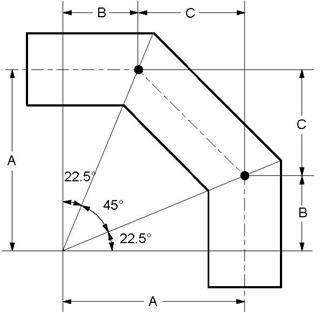 Two Miter Cuts (N=2)
q = 90° / ( 2 x 2 ) = 22.5°
S = 2 A tan q = 0.828427 A
B = A tan q = 0.414214 A
C = 2 A tan q cos 2q = 0.585786 A
Closely Spaced
The miter is Closely spaced if,
S < r ( 1 + tan q )
Substituting for S,
2A tan q < r ( 1 + tan q )
A < 1.707107 r
Bend radius, R = 0.5 S cot q = A
Widely Spaced
R = 0.5 r ( 1 + cot q ) = 1.707107 r
Three Miter Cuts (N=3)
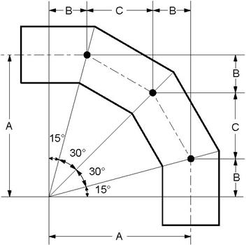 q = 90° / ( 2 x 3 ) = 15°
S = 2 A tan q = 0.535898 A
B = A tan q = 0.267949 A
C = 2 A tan q cos 2q = 0.464102 A
Closely Spaced
The miter is Closely spaced if,
S < r ( 1 + tan q )
Substituting for S,
2A tan q < r ( 1 + tan q )
A < 2.366025 r
Bend radius, R = 0.5 S cot q = A
Widely Spaced
R = 0.5 r ( 1 + cot q ) = 2.366025 r
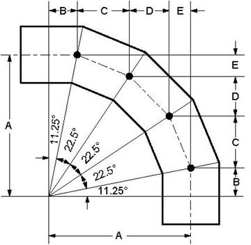 Four Miter Cuts (N=4)
q = 90° / ( 2 x 4 ) = 11.25°
S = 2 A tan q = 0.397825 A
B = A tan q = 0.198912 A
C = 2 A tan q cos 2q = 0.367542 A
D = 2 A tan q sin 4q = 0.281305 A
E = 2 A tan q sin 2q = 0.152241 A
Closely Spaced
The miter is Closely spaced if,
S < r ( 1 + tan q )
Substituting for S,
2A tan q < r ( 1 + tan q )
A < 3.013670 r
Bend radius, R = 0.5 S cot q = A
Widely Spaced
R = 0.5 r ( 1 + cot q ) = 3.013670 r
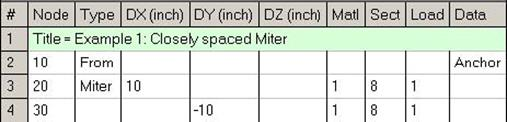
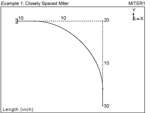
Example 1: Closely Spaced Miter
Example Data
Pipe OD = 8.625”, thickness, t = 0.322”
Mean pipe radius, r = (8.625 - 0.322) / 2 = 4.1515”,
Number of miter cuts = 3,
Dimension A = 8”, See 3-cut miter figure.
Look up table (Miter modeling procedure), for an outline of the modeling procedure.
First, determine the type of miter (Closely or Widely spaced) before modeling it.
Look up Summary of Miter parameters, for N = 3. A miter is Closely spaced if A < 2.366025r. This condition is true for r = 4.1515”. Hence, this is a Closely spaced miter.
Steps for Example 1
u Create From node: When you start a new model file, node 10 and an Anchor are automatically input, press Enter to move cursor to next empty row.
u Construct miter bend: type 20 for Node (simply pressing Tab puts this node number automatically for you), type “m” under the Type column, type 8” for bend radius, select Closely spaced, click on Ok. Type 10” for DX, enter material, section and load names, press Enter.
u Finish the miter bend: type 30 for Node and -10” for DY, press Enter.
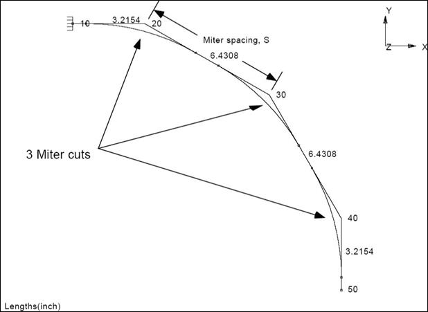
Example 2: Widely Spaced Miter
Let us assume the same data as in Example 1 (Closely spaced miter) with only one change, namely, dimension A (see next figure).
Mean pipe radius, r = (8.625 - 0.322) / 2 = 4.1515”,
Number of miter cuts = 3,
Dimension A = 12”.
Look up table (for Miter modeling procedure) for an outline of the modeling procedure.
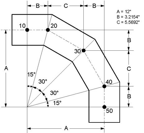
It is essential to determine the type of miter (Closely or Widely spaced) before modeling it.
Determine miter type
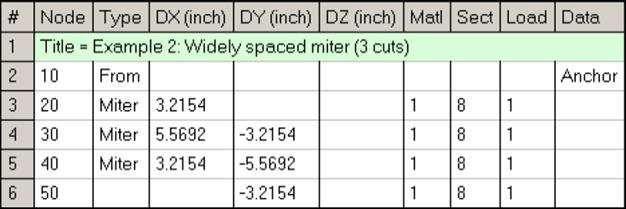
Look up table, Summary of Miter parameters, for N = 3. A miter is Closely spaced if A < 2.366025r. This condition is false for r = 4.1515”. Hence, this is a Widely spaced miter. This miter bend has to be modeled as a series of 3 miters. Next, observe in this table that dimensions B, C and R (Equivalent miter bend radius) can be calculated for N = 3 cuts.
Calculate required dimensions
With r = 4.1515”,
Equivalent miter bend radius, R = 2.366025 × r = 9.8225”,
Dimension B = 0.267949 × A = 3.2154”,
Dimension C = 0.464102 × A = 5.5692”
See previous figure. After calculating B, C and R, let us now calculate the offsets of nodes 20, 30 and 40 (the 3 nodes correspond with the 3 miter cuts).
Calculate Offsets
Offsets of node 20 from 10: (First miter cut)
DX = B = 3.2154”
DY = 0” (because node 20 is on the horizontal axis).
Offsets of node 30 from 20: (Second miter cut)
DX = C = 5.5692”
DY = -B = -3.2154”
Offsets of node 40 from 30: (Third miter cut)
DX = B = 3.2154”
DY = -C = -5.5692”
Offsets of node 50 from 40:
DX = 0” (because node 50 is on the vertical axis).
DY = -B = -3.2154”
Now, start to build the model in CAEPIPE as shown in Example 1 but with different data (bend radius = 9.8225”, select Widely Spaced miter, and offsets as shown above).
Steps for Example 2
u Create From node: When you start a new model file, node 10 and an Anchor are automatically input, press Enter to move cursor to next empty row.
u Construct first miter bend: type 20 for Node (simply pressing Tab puts this node number automatically for you), type “m” under the Type column, type 9.8225” for bend radius, select Widely spaced, click on Ok. Type 3.2154” for DX, enter material, section and load names, press Enter.
u Construct second miter bend: type 30 for Node (simply pressing Tab puts this node number automatically for you), type “m” under the Type column, type 9.8225” for bend radius, select Widely spaced, click on Ok. Type 5.5692” for DX, -3.2154” for DY, press Enter.
u Construct third miter bend: type 40 for Node (simply pressing Tab puts this node number automatically for you), type “m” under the Type column, type 9.8225” for bend radius, select Widely spaced, click on Ok. Type 3.2154” for DX, -5.5692” for DY, press Enter.
u Finish the miter bend: type 50 for Node and -3.2154” for DY, press Enter.
 Sherwood, David. R., and Dennis J. Whistance. THE “PIPING GUIDE” A Compact Reference for the Design and Drafting of Industrial Piping Systems. First Edition (revised). San Francisco: Syentek Books Co., 1980.