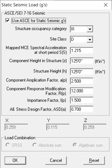
Static Seismic Load – ASCE/SEI 7-16
Guidelines from ASCE/SEI 7-16 “Minimum Design Loads for Buildings and Other Structures” are explained below.
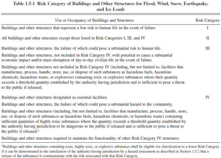
Structure Occupancy Category (Risk Category):
Table 1.5-1 of ASCE/SEI 7-16 provides the Risk Category of Buildings and Other Structures for Flood, Wind, Snow, Earthquake, and Ice Loads Structure. Based upon your project specification, select the Structure Occupancy Category from the options available.
Site Class:
Based on the site soil properties, the site shall be classified as Site Class A, B, C, D, E & F.
Refer Chapter 20 of ASCE/SEI 7-16 for details on Site Class. Depending on your project specification, select the Site Class from the options provided.
Note: Para. 11.4.3 of ASCE/SEI 7-16 states that “Where the soil properties are not known in sufficient detail to determine the site class, Site Class D shall be used unless the authority having jurisdiction or geotechnical data determines Site Class E or F soils are present at the site”.
Mapped MCE Spectral Acceleration at Short Period S(S):
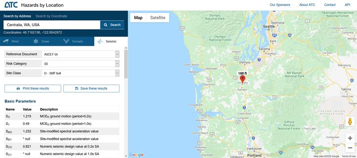
The USGS maintains a website http://earthquake.usgs.gov/designmaps with which the site latitude and longitude, as well as the value of S(S) can be retrieved.
For example, for Centralia, WA, the value of S(S) is retrieved as 1.125 with Structure Occupancy Category III and Site Class D from the link https://hazards.atcouncil.org as shown below.
Component Height in Structure (z)
Component Height in Structure (z) is the point of attachment of components with respect to the base. As per para. 13.3.1 of ASCE/SEI 7-16, for components at or below the base, z shall be taken as 0. In addition, the value of z/h need not exceed 1.0.
For example, for a Piping attached to a Boiler Nozzle located at an Elevation 150’0” with a Ground Level of 25’0”, z can be computed as 125’ (= 150’ – 25’).
Structure Height (h)
Structure height (h) is the average roof height of the structure with respect to the base. From the above example, the average roof height of structure (h) with respect to the base can be calculated as 125’ (= 150’ – 25’).
Component Amplification Factor, a(p)
Table 13.6-1 Seismic Coefficients for Mechanical and Electrical Components of ASCE/SEI 7-16 provides values of Component Amplification Factor “a(p)” for various components. As per para. 13.3.1 of ASCE/SEI 7-16, the component amplification factor is from 1.00 to 2.50.
For example, Piping in accordance with ASME B31, including in-line components with joints made by welding or brazing, the value of Component Amplification Factor “a(p)” is listed as 2.50.
Component Response Modification Factor, R(p)
Table 13.6-1 Seismic Coefficients for Mechanical and Electrical Components of ASCE/SEI 7-16 provides values of Component Response Modification Factor “R(p)” for various components. As per para. 13.3.1 of ASCE/SEI 7-16, component response modification factor should be from 1.00 to 12.00
For example, Piping in accordance with ASME B31, including in-line components with joints made by welding or brazing, the value of Component Response Modification Factor “R(p)” is listed as 12.00.
Importance Factor, I(p)
Para. 13.1.3 of ASCE/SEI 7-16 provides a guideline to arrive at component Importance Factor “I(p)”. The value of “I(p)” can be between 1.0 and 1.5.
Allowable Stress Design Factor, ADS(a)
Enter Allowable Stress Design Factor, ADS(a) as specified in the project specification. If this data is not available, then it can be specified as 1.0.
Para. 13.1.8 of ASCE/SEI 7-16 states that the earthquake loads determined in accordance with Section 13.3.1 of ASCE/SEI 7-16 shall be multiplied by an Allowable Stress Design Factor ADS(a) of 0.7.
Example:
For a power plant required to operate in an emergency, located in Centralia, WA, USA, with Occupancy Category as III, Site Class as D (with Stiff soil) and Importance Factor 1.5, use ASCE/SEI 7-16 and compute the design earthquake load coefficient for piping required to operate the plant.
1. From the map above with Occupancy Category as III and Site Class as D, the Mapped MCE Spectral Acceleration at Short Period ‘S(S)” = 1.215.
2. Component Height in Structure (z) = 150’0” – 25’0” = 125’0”
3. Structure Height (h) = 150’0” – 25’0” = 125’0”
4. Component Amplification Factor, a(p) = 2.50 (as per Table 13.6-1 of ASCE/SEI 7-16, for Piping in accordance with ASME B31, including in-line components with joints made by welding or brazing)
5. Component Response Modification Factor, R(p) = 12.00 (as per Table 13.6-1 of ASCE/SEI 7-16, for Piping in accordance with ASME B31, including in-line components with joints made by welding or brazing)
6. Importance Factor, I(p) = 1.5 (given)
With the data provided above,
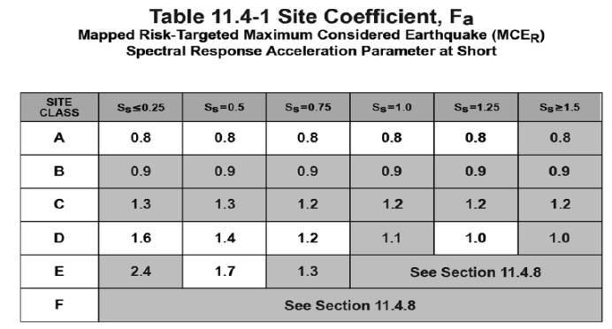
a. Site Coefficient at Short Period, F(a) = 1.014 (as per Table 11.4-1 for S(S) = 1.215 is and Site Class D)
b. As per equation 11.4-1 of ASCE/SEI 7-16, Maximum MCE Spectral Acceleration at Short Period S(MS) = F(a)*S(S) = 1.014 * 1.215 = 1.232 g
c. As per equation 11.4-3 of ASCE/SEI 7-16, Design Spectral Acceleration at Short Period S(DS) = (2/3)*S(MS) = (2/3)*1.232 = 0.821 g
d. As per equation 13.3-1 of ASCE/SEI 7-16,
Horizontal Seismic g-load value = H(g) = 0.4*S(DS)*[a(p)/R(p)]*I(p)*[1 + 2(z/h)]
= 0.4*0.821*(2.5/12.0)*1.50*[1+(2*(125/125))] = 0.308 g
e. As per equation 13.3-2 of ASCE/SEI 7-16,
Maximum Horizontal Seismic g-load value H(g.max) = 1.6*S(DS)*I(p)
= 1.6*0.821*1.5 = 1.97 g
f. As per equation 13.3-3 of ASCE/SEI 7-16,
Minimum Horizontal Seismic g-load value H(g.min) = 0.30*S(DS)*I(p)
= 0.30*0.821*1.5 = 0.369 g
g. As per Para 13.3.1 of ASCE/SEI 7-16,
Vertical Seismic g-load V(g) = 0.20*S(DS)
= 0.20*0.821 = 0.164 g
As per Para. 13.3.1 of ASCE/SEI 7-16, H(g) >= H(g.min) and H(g) <= H(g.max)
Hence,
Horizontal Seismic g-load value H(g) = 0.369 g.
Vertical Seismic g-load value V(g) = 0.164 g
From the above, as per Para. 13.1.7 of ASCE/SEI 7 – 16,
Allowable Stress Design Horizontal Seismic g-load value = H(g)*ADS(a)
= 0.369 * 0.70 = 0.258 g
Allowable Stress Design Vertical Seismic g-load value = V(g)*ADS(a)
= 0.164 * 0.70 = 0.115 g
CAEPIPE Output