Displacements
Displacements for all load cases can be shown (operating load case shown here). Click on the black left/right arrow to show displacements for other load cases. You can show the deflected shape in the graphics window for any load case by clicking on the button to the left of the “A” button.
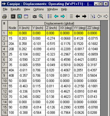
You can animate the same deflected shape by clicking on Show animated deflected shape (last) button in the toolbar.
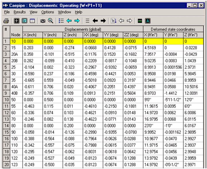
You have the option of showing the deformed state coordinates in the global coordinate system along with the displacements at each node. Is snapshot below updated from V8.0?
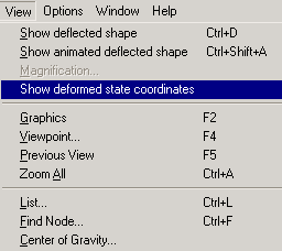
These deformed state coordinates are useful in locating hanger attachment points on the steel structures or concrete slabs/walls from which the hangers are to be hung, such that the hangers remain almost “vertical” (and not skewed) during normal operating load case.
Also, you can show Minimum/Maximum displacements, displacements at flexible joints (if any) by clicking on the Other displacements button and selecting the item of interest (or by clicking on the left/right white arrows).
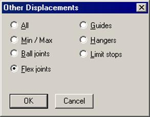
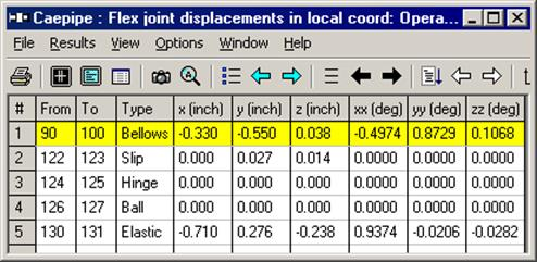
Displacements in local coordinates for all flexible joints (bellows, ball, hinge, etc.) are shown under Flex joints.
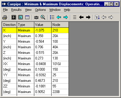
Minimum/Maximum displacements for each load case can be shown (Operating load case shown below). You can show minimum/maximum displacements for other load cases by clicking on the black arrows.
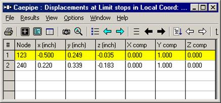
Displacements at “Other supports” can be shown (limit stops shown here).