Fatigue Cycles
Starting CAEPIPE Version 13.00, both Simplified Fatigue Evaluation and Detailed Fatigue Evaluation can be performed as stated in the Sections titled “Simplified Fatigue Evaluation” and “Detailed Fatigue Evaluation” of this manual.
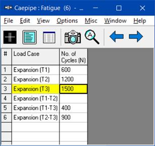
Actual Number of Thermal Cycles corresponding to each Expansion Load case selected for the evaluation can be input through this option. These data are required for Simplified Fatigue Evaluation as well as for Detailed Fatigue Evaluation.
Note:
CAEPIPE will exclude those Expansion load cases where the “No. of Cycles” column is left BLANK from Simplified Fatigue and Detailed Fatigue Evaluation. After inputting the Actual No. of Cycles, turn ON the Simplified Fatigue and/or Detailed Fatigue through Loads menu.
Example Calculation
Assume a piping system experiences the following cyclic loading conditions:
· Expansion (T1): Alternating Stress amplitude of 15000 psi, with 5000 cycles.
· Expansion (T2): Alternating Stress amplitude of 30000 psi, with 2000 cycles.
The Alternating stress amplitudes listed above are one-half of the stress range values (=SE/2.0) at a particular Node for Expansion (T1) and Expansion (T2) cases respectively.
From the sample S-N curve given below,
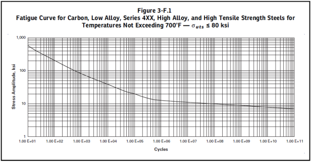
· At Alternating Stress 15000 psi: N1 (Number of cycles to failure) = 1E+6 cycles.
· At Alternating Stress 30000 psi: N2 (Number of cycles to failure) = 1E+4 cycles.
Calculate damage:
· Damage at 15000 psi: n1/N1 = 5000/1E+6 = 0.005
· Damage at 30000 psi: n2/N2 = 2000/1E+4 = 0.200
· Total Cumulative Damage: D = 0.005 + 0.2 = 0.205
Since D < 1.0, the component meets the Fatigue requirement for the given cyclic loading conditions, though it will have consumed 20.5% of its total allowable fatigue life.
Actual Number of Cycles to be Input for Simplified and Detailed Fatigue Analysis:
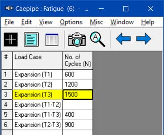
In CAEPIPE, the actual number of cycles associated with each selected expansion load case can be entered as shown below. When Simplified or Detailed Fatigue Analysis is enabled, CAEPIPE utilizes this table (containing the actual number of cycles for the selected load cases) to perform both Simplified and Detailed Fatigue Analysis. Please note, as stated above, when any of the load cases is not to be included in the Fatigue Evaluation, then leave the ‘Number of Cycles (N)’ field for that load case BLANK as shown below.
When Simplified Fatigue Analysis is turned ON, CAEPIPE uses the above table for calculating the “equivalent reference displacement stress range cycles (N)”, which then is used to compute the stress range reduction factor (‘f’ or ‘U’) as detailed in the section titled ‘Simplified Fatigue Evaluation’ in the CAEPIPE Code Compliance Manual.
Similarly, when the Detailed Fatigue Analysis is turned ON, CAEPIPE uses the above table to compute the “Cumulative Damage (D)” as outlined in the section titled ‘Detailed Fatigue Evaluation’ in the CAEPIPE Code Compliance Manual.
For better clarity, refer to the example given below for inputting the Fatigue Cycle table:
Consider a piping system that operates at three different temperature levels, each with a corresponding number of cycles over its service life and with the reference temperature of  .
.
20 cycles of 
10 cycles of 
100 cycles of
With reference to the above temperature ranges, the number of cycles that can be entered in CAEPIPE for each load case are as follows.
· For Expansion  , the number of cycles=20
· For Expansion  , the number of cycles=10
· For Expansion  , the number of cycles=100
· For Expansion  , the number of cycles = Min(
  = Min(20,10) = 10
· For Expansion  , the number of cycles = Min(
  = Min(20,100) = 20
· For Expansion  , the number of cycles = Min(
  = Min(10,100) = 10
Accordingly, the Fatigue Cycle table in CAEPIPE is to be input as shown below.
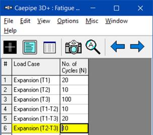
The above approach to input the number of cycles is conservative as the sum of the Number of Cycles input is greater than the sum of actual number of cycles (i.e., [170 = 20+10+100+10+20+10] > [130 = 20+10+100]). There may be alternate ways to input the number of cycles, such as “combining” or "lumping" the ranges of variations to produce the maximum effect as stated in Clause NB-3553 ‘Fatigue Usage’ of ASME Section III, Subsection NB (2021).