Slope
You can specify the slope of the line you want to model for an element, in terms of its direction cosines (DCs).
This command calculates the offsets automatically for a sloping element (that does not align with one of the major global axes). When a pipe slopes (or is routed at an angle) with respect to the global axes, it becomes necessary to calculate the offsets (DX, DY and DZ) using those faithful sine and cosine functions. But, therein lies the problem. Sometimes, calculations get tricky and time-consuming.
Let us see a few examples.
Example 1: A 20° line in the XZ plane, 10 feet long
Method 1:
Calculate the offsets:
DX = 10 cosine (20) = 9.4 (ft.), DZ = 10 sine (20) = 3.42 (ft.). Simple!
Method 2:
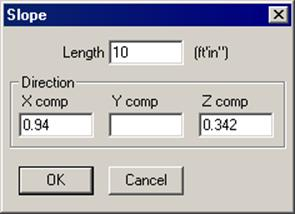
Find direction cosines (DCs) for the line (vector). Direction cosines are simply cosines of the angles the vector makes with the global X-, Y- and Z-axes. In this case, A=20° (X), B=90° (Y), C=70° (Z). Cosines of these angles are: X comp=0.94, Y comp=0, Z comp=0.342.
Now, position the cursor on the sloping element row, right click under DX/DY/DZ. Select Slope from the menu, enter these numbers into the X comp, Y comp and the Z comp fields of the Slope dialog that opens, and type the length, 10 ft. Press Enter. CAEPIPE calculates the respective offsets using the DCs you input.
Once you input the slope, follow this pipe with other elements down the line by inputting different lengths while you retain the same direction cosines.
Example 2: A 40° line in the X(-Y) plane
Method 2:
Find direction cosines, if the line is at 40 deg. to X-axis in X(-Y) plane, it makes 50° with the (-Y) axis. So, the DCs are: cos (40°) = 0.766, cos (50°) = 0.643, So, X comp = 0.766, Y comp = -0.643, Z comp = 0.0. Type these DCs and a length into the Slope dialog. Press Enter.
More information about Direction cosines is available under the section on Direction in the Technical Reference Manual.