Static Seismic Loads
All Piping Codes excepting “None” and “EN13941”
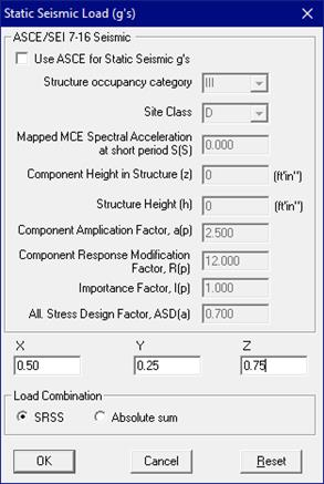
You can enter up to three (3) Static Seismic loads namely Seismic 1, Seismic 2, and Seismic 3.
Use these loads to apply static seismic loads (g-loads) computed using ASCE/SEI 7-16 or entered directly to the model. CAEPIPE applies the g-load to the piping system mass separately for X, Y and Z directions for each Seismic load case. The computed results (displacements, forces and moments) from each of the three (internal) load cases (i.e., one case corresponding to each global directional g-load) are then combined using your choice of Absolute sum or Square root of sum of squares (SRSS).
Since either the “SRSS” or “Absolute sum” is always turned ON under Load Combination, static seismic is always an unsigned case and hence, you will not see a sign (+ or –) in the results for this load case.
Under menu Loads > Load cases, check the box next to Static Seismic (g’s) to select this case for analysis. This load is treated as an Occasional load.
The g-loads are applied only in the specified direction, i.e., a Z (g-load) of -0.189 is applied only in the -Z direction, and not in +Z direction.
A g-load input may affect the extracted natural frequencies when no piping code is selected (i.e., Piping code = None). See under “Dynamics > Cutoff Frequency” for how.
Acceleration in the vertical direction, if not provided explicitly, is generally taken to be 75% of the g-load in the horizontal directions.
The g-load values can be calculated from any of the several sources available (ASCE/SEI 7-16, ASCE A58.1, UBC, etc.). Refer to Section titled “Static Seismic Load” in CAEPIPE Technical Reference Manual for details on the implementation of ASCE/SEI 7-16 in CAEPIPE starting Version 10.30 and manual calculation as per ANSI A58.1.
Static Seismic Analysis
CAEPIPE computes the inertia force (as mass * acceleration) for each direction and applies it as an occasional load. The g-loads for the above example are 0.50g in the global X, 0.75g in the global Z, and then 0.25g in the vertical Y direction. CAEPIPE applies an X acceleration (of 0.50g) first and solves the case. This procedure is then repeated to apply accelerations in Y and Z directions as independent cases and obtain the corresponding results.
The above procedure results in three sets of solutions (displacements, element forces and moments, and support loads) to acceleration loads in X, Y and Z directions, which are typically combined in some manner. In CAEPIPE, two directional combination methods are available: SRSS (Square root of sum of squares) and ABS (Absolute).
In the SRSS method, each directional component of displacements, element forces and moments, and support loads from the three X, Y and Z acceleration analyses are squared individually and added. The square roots of these respective sums are the displacement, element force and moment, and support load at a given node. InABS method, all absolute values of each directional component of displacements, element forces and moments, and support loads are added to get the absolute values for total displacements, element forces and moments, and support loads.
The occasional stresses are added to sustained stresses(
 ) and shown under Occasional stresses
  .
.
CAEPIPE does not include piping system weight in Seismic load case, a few reasons being:
1. The weight is already included in Sustained load case, and
2. Piping codes such as B31.3 specifically mention that MA and MB calculations (moments due to sustained and occasional loads respectively) be done separately before combining them to calculate Occasional stresses .
If you can, avoid nonlinearities such as gaps and friction when your analysis includes seismic loads. As it is, Static Seismic analysis is an approximation of Response Spectrum analysis, which is, in turn, an approximation of Time History analysis for a seismic event wherein seismic accelerations are applied as a function of time only at piping supports! So, the result you get from a static seismic analysis is a gross approximation.
CAEPIPE adds the support loads from a static seismic case to those from Sustained and Operating load cases to produce the combination loads at supports. Look under the Support load summary to get the different combination loads at each support.
In linear analysis (i.e., no gaps and no friction), the results from a seismic load in +X and –X directions should be the same. So, the combination ranges can be seen by studying support load summary (e.g., Sustained+Seismic, Sustained–Seismic).
In nonlinear analysis, however, the results from a seismic load in +X may NOT be the same as those from –X. In such a case, you will have to make two runs, i.e., analyze the original (say, model1.mod) with +X g-load; copy the model to model2.mod, specify a –X g-load and compute results. Now you have two sets of results, one from each model. Compare the two results carefully to identify the range (least to the most).
Or, for further post processing, export the results from each model to a CSV file via the Print > Print to File command (select file type as: CSV). Import each CSV file into a spreadsheet (e.g., MS-Excel) and combine the results of interest manually.
In summary, you can set up as many runs as required for the g-loads (+ or –), depending on whether your model is linear or non-linear, and export results for those runs that you cannot combine inside CAEPIPE.
As another example, for a nonlinear model with g-loads only in the X-Y plane, you can analyze four runs (or four identical models with four different seismic loads) thus:
Run 1. Specify +X/+Y g-load
Run 2. Specify -X/-Y g-load
Run 3. Specify -X/+Y g-load
Run 4. Specify +X/-Y g-load
Examine the seismic and combination forces and moments from all runs, or in a spreadsheet (using the .CSV files CAEPIPE exports for each model) to determine the most conservative of results (and range) for further interpretation.
As another example, in a linear model with g-loads only in the X-Y plane, the two runs
Run 1. Specify +X/-Y g-load
Run 2. Specify -X/+Y g-load
are the same. So, either case (run) alone is adequate.
Or, another example, for a nonlinear model with g-loads in all three global directions, you could set up eight runs/models:
Run 1. Specify +X/+Y/+Z g-load
Run 2. Specify +X/+Y/-Z g-load
Run 3. Specify +X/-Y/+Z g-load
Run 4. Specify +X/-Y/-Z g-load
Run 5. Specify -X/+Y/+Z g-load
Run 6. Specify -X/+Y/-Z g-load
Run 7. Specify -X/-Y/+Z g-load
Run 8. Specify -X/-Y/-Z g-load
Each of these runs may yield different results. So, a careful evaluation of all eight runs is necessary to identify the most conservative solution and/or determine a range.
“None” Code
For “None” code, you can input only one (1) Static Seismic case as CAEPIPE performs only “Static analysis”, which includes weight, one (1) pressure, one (1) thermal, cold spring, static seismic and one (1) wind load, all applied at the same time.
Static seismic load (g-loads) can be computed using ASCE/SEI 7-16 or entered directly to the model. CAEPIPE applies the g-load to the piping system masses separately for each of X, Y and Z directions for the Seismic load case. The computed results (displacements, forces and moments) from each of the three (internal) load cases (i.e., one case corresponding to each global directional g-load) are then combined using Algebraic Sum for “None” code as shown in the figure below.
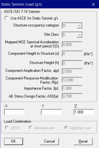
Similarly, the Specified Displacement results for Static Seismic load are “Algebraically” added to the results from all other load cases.
In addition, CAEPIPE will always include "-1G" in the Vertical direction to account for the total weight of the piping/tubing/ducting including its content, irrespective of the value of Vertical G factor specified through CAEPIPE Layout Window > Loads > Static Seismic 1 for the “NONE” code. For example, if you wish to analyze your piping/tubing/ducting for "pure" +3G upward, then you need to input +4G Vertically under Static Seismic 1 to simulate “pure” +3G upward.
EN 13941 Code
For “EN13941”, Static Seismic cannot be input as the piping code does not require Seismic loads to be included for analysis.