

For information on Piping Stress Analysis, click on the link below
CAEPIPE Product Information
Download Free Evaluation Request Pricing
Basic Pipe Stress Analysis Tutorial
Tutorial: Table of Contents
Technical Article: Pipe Stress Analysis Procedure
Example 1: Using Expansion Loops
Example 2: Splitting Thermal Growth
Example 3: Axial Restraints to Direct Thermal Growth
Basic Pipe Stress Concepts
Piping systems experience different loadings, categorized into three basic loading types listed below.
Sustained Load:
It mainly consists of internal pressure and dead-weight. Dead-weight is from weight of pipes, fittings, components such as valves, operating fluid, insulation, cladding, lining etc.
Internal design/operating pressure develops uniform circumferential stresses in the pipe wall, based on which pipe wall thickness is determined during the process/P&ID stage of plant design such that piping "failure by rupture" is avoided. In addition, internal pressure develops axial stresses in the pipe wall. These axial pressure stresses vary only with pressure, pipe diameter and wall thickness, which are already pre-set at the P&ID stage and hence these axial pressure stresses cannot be reduced by changing the piping layout or the pipe support scheme.
On the other hand, dead-weight causes the pipe to bend (generally downward) between supports and nozzles, producing axial stresses in the pipe wall (also called "bending stresses"); these bending stresses linearly vary across the pipe cross-section, being tensile at either the top or bottom surface and compressive at the other surface. If the piping system is not supported in the vertical direction (i.e., in the gravity direction) excepting at equipment nozzles, bending of the pipe due to dead-weight may develop excessive stresses in the pipe and impose large loads on equipment nozzles, increasing the susceptibility to piping "failure by collapse".
Various international piping codes impose limits, also called "allowable stresses for sustained loads", on these axial stresses generated by dead-weight and pressure in order to avoid "failure by collapse".
For the calculated axial stresses to be below such allowable stresses for sustained loads, it may be necessary to support the piping system vertically. Typical vertical supports to carry dead-weight are:
a) Resting steel supports,
b) Rod hangers,
c) Variable spring hangers, and
d) Constant support hangers..
Both rod hangers and resting steel supports fully restrain downward pipe movement but permit pipe to lift up at such supports. If pipe lifts up at any of the rod hangers / resting supports during operating condition, then that support does not carry any pipe weight and hence will not serve its purpose.
In the below Section, a couple of sample layouts are presented to illustrate how piping can be supported by spring hangers and resting steel supports to comply with the code requirements for sustained loads.
Thermal Load (also referred as Expansion Load):
It refers to the "cyclic" thermal expansion/contraction of piping as the system goes from one thermal state to another thermal state (for example, from "shut-down" to "normal operations" and then back to "shut-down"). If the piping system is not restrained in the thermal growth/contraction directions (for example, in the axial direction of a straight pipe), then for such cyclic thermal load, the pipe expands/contracts freely; in this case, no internal forces, moments and resulting stresses and strains are generated in the piping.
If, on the other hand, the pipe is "restrained" in the directions it wants to thermally deform (such as at equipment nozzles and pipe supports), such constraint on free thermal deformation generates cyclic thermal stresses and strains throughout the system as the system goes from one thermal state to another. When such calculated thermal stress ranges exceed the "allowable thermal stress range" specified by various international piping codes, then the system is susceptible to "failure by fatigue". So, in order to avoid "fatigue failure" due to cyclic thermal loads, the piping system should be made flexible (and not stiff). This is normally accomplished as follows:
a) Introduce bends/elbows in the layout, as bends/ elbows "ovalize" when bent by end-moments, which increases piping flexibility.
b) Introduce as much "offsets" as possible between equipment nozzles (which are normally modeled as anchors in pipe stress analysis). For example, if two equipment nozzles (which are to be connected by a pipeline) are in line, then the straight pipe connecting these nozzles is "very stiff". If, on the other hand, the two equipment are located with an "offset", then their nozzles will have to be connected by an "L-shaped" pipeline which includes a bend/elbow; such "L-shaped" pipeline is much more flexible than the straight pipeline mentioned above.
c) Introduce expansion loops (with each loop consisting of four bends/elbows) to absorb thermal growth/contraction.
d) Lastly, introduce expansion joints such as bellows, slip joints etc., if warranted.
In addition to generating thermal stress ranges in the piping system, cyclic thermal loads impose loads on static and rotating equipment nozzles. By following one or more of the steps from (a) to (d) above and steps (e) and (f) listed below, such nozzle loads can be reduced.
e) Introduce "axial restraints" (which restrain pipe in its axial direction) at appropriate locations such that thermal growth/contraction is directed away from equipment nozzles, especially critical ones.
f) Introduce "intermediate anchors" (which restrain pipe movement in the three translational and three rotational directions) at appropriate locations such that thermal deformation is absorbed by regions (such as expansion loops) away from equipment nozzles.
In the below Section titled "Sample Pipe Stress Problems and Solutions", a few sample layouts are presented to illustrate how loops/offsets, axial restraints and intermediate anchors are used to reduce thermal stresses in piping (and resulting nozzle loads).
Occasional Loads:
These are the third type of loads, which are imposed on piping by occasional events such as earthquake, wind etc. To protect piping from wind (which normally blows in horizontal plane), it is normal practice to attach "lateral supports" to piping systems. During an earthquake, the earth may also move vertically. To protect piping against both horizontal and vertical movement during earthquake, "integral 2-way vertical and lateral restraints" are required.
In summary, to carry sustained loads, normally vertical weight supports (as those listed under the Section titled "Sustained Load" above) are required. To safeguard piping from wind, lateral restraints can be added to some of the vertical weight supports (especially resting steel supports). Similarly, to withstand static seismic 'g' loads, some of the vertical weight supports can be modified as "integral 2-way vertical and lateral restraints". Lastly, for thermal loads, zero supports give zero stresses. So, thermal stresses and equipment nozzle loads will normally decrease as the number of supports goes down. Axial restraints and intermediate anchors are recommended only to direct thermal growth away from equipment nozzles.
Pipe Stress Analysis: Procedure
Step1: Generating CAEPIPE model
Model the piping system in CAEPIPE (either directly inside CAEPIPE, or by using one of SST's data translators to import the piping model) and follow the steps shown in the CAEPIPE Tutorial to learn the basics of operating CAEPIPE to create and analyze a model and review its results. Once all the data is in, Analyze. Now, review Results.
Step2: Studying Thermal Stress results for the Initial Layout
Review first stress contour plot for thermal stresses. The plot is color-coded such that "blue" region denotes areas with the least stress ratios (where stress ratio equals to actual computed stress divided by allowable thermal stress), "green" region with higher stress ratios, "yellow" region with even higher stress ratios, and "red" region with the highest stress ratios. Intermediate areas between these distinct colors will be of "bluish-green", "greenish-yellow" and "orange" colors.
Since thermal stresses generated are directly dependent on how "flexible" the layout is, it may be necessary to make the layout as "flexible" as possible (by including bends, offsets, loops etc.) to reduce thermal stresses. So, the goal is to arrive at a "flexible" layout for which thermal stress ratios remain within "blue" to "yellow" range and not get into "orange" and "red" zones. For a more "flexible" layout, even "yellow" zone may be avoided. That would leave even more thermal margin for stress engineers to meet other pipe stress criteria not considered under first-level stress checks.
Step 3: Finalizing Layout to meet Thermal Stress criteria
In case thermal stress ratios exceed "yellow" zone (i.e., "orange" and "red" zones appear in one or more areas of the piping system), it is important to study the deformed shape for "thermal" load case in order to understand how the piping deforms for "pure thermal" load (where only temperature change is considered). By studying such deformed shape, it is possible to arrive at a layout with appropriate bends, offsets and loops and/or with appropriately located axial restraints/intermediate anchors such that thermal stress ratios do not exceed "yellow" zone. This process may require several iterations on layout and/or locations for axial restraints/intermediate anchors.
Step 4: Studying Results for Sustained Load
After finalizing piping layout under Steps 2 and 3 for thermal loading, the next task is to support the system vertically to carry its own deadweight under operating condition. In this connection, first review stress contour plot shown in color codes from "blue" to "red" (as in Step 2 above) for sustained stress ratios generated by deadweight and pressure for the system without any vertical supports (excepting those provided by equipment nozzles and intermediate anchors introduced in Step 3 above).
The goal is to arrive at a vertical support scheme consisting of (a) resting steel supports, (b) rod hangers, (c) variable spring hangers and (d) constant support hangers, at appropriate locations (where such pipe supports can be attached to adjacent concrete/steel structures, platforms etc.) so that stress contour plot for sustained stress ratios avoids "orange" and "red" zones and remains within "blue to yellow" range.
Step 5: Finalizing Vertical Supports to carry Sustained Load
In case sustained stresses exceed "yellow" zone in one or more areas of the piping system, study the deformed shape provided by CAEPIPE for sustained load case in order to understand how the piping responds to its own deadweight. Next, identify pipe locations in the 3D model where the pipe can be vertically supported by the support types listed under Step 4 above. Based on this input, vertically support the piping such that sustained stresses do not exceed "yellow" zone. This step may require to execute CAEPIPE on the system with several different locations for weight supports.
CAEPIPE automatically sizes spring hangers wherever such hangers are located in the 3D model.
In case resting steel supports are selected to provide vertical support for piping under sustained load, it is to be made sure that piping continues to rest on such steel supports even during operating condition (= weight + pressure + thermal) and does not lift off from these supports. If pipe lifts up at any of these resting supports during operating condition, then that support does not carry any pipe weight under operating condition and hence will not serve its purpose. Similarly, at rod hanger locations, the tendency of piping should be to deform downward for operating load case, so that the rod hangers carry the pipe weight under tension. On the other hand, if pipe lifts up at any of the rod hangers, then that rod hanger goes into compression thereby not carrying the weight of the piping during operating condition. Whether the pipe weight is being carried during operation by resting steel supports and/or rod hangers (both types are mathematically modeled as one-way vertical Limit Stops in CAEPIPE) or whether the pipe lifts up at those support locations is shown in the report titled "Status of Limit Stops - Operating Load". The goal is to make sure the status is shown as "Reached" at all vertical Limit Stops for Operating Load case.
Step 6: Studying Results for Static Seismic "g" Load
After arriving at a final layout with an acceptable pipe support scheme under Steps 2 to 5 for thermal and sustained loads, the next task is to protect piping against large horizontal and vertical movements that could occur due to static seismic "g" load.
To accomplish this goal, first review stress contour plot for occasional stresses generated by deadweight, pressure and static seismic "g" load shown in color codes from "blue" to "red" (as in Step 2 above).
The goal is to replace some of the weight supports (for example, resting supports) located in the "yellow" to "red" zones with "integral 2-way vertical and lateral restraints", so that stress contour plot for occasional stresses avoids "orange" and "red" zones and remains within "blue to yellow" range.
Step 7: Finalizing 2-way Vertical and Lateral Restraints to withstand Static Seismic "g" Load
In case occasional stresses exceed "yellow" zone in one or more areas of the piping system, study the seismic deformed shape provided by CAEPIPE in order to understand how the piping responds to static seismic "g" load. Next, identify those weight support locations (for example, resting supports) in the "yellow" to "red" zones where the pipe can also be laterally supported and replace those weight supports with "integral 2-way vertical and lateral restraints", such that occasional stresses do not exceed "yellow" zone. This step may require to execute CAEPIPE on the system with several different locations for "integral 2-way vertical and lateral restraints".
Step 8: Meeting Allowable Loads at Nozzles / Anchors
After locating relevant supports (a) to minimize thermal stresses, (b) to carry weight of the piping during operation, and (c) to withstand static seismic "g" load, the analyst should check the calculated loads at nozzles/anchors in the Support Load Summary. If the calculated loads at nozzles/anchors exceed the corresponding Allowable Loads, by studying the deformed shapes provided by CAEPIPE for different load cases, it is possible to further modify the layout and/or support scheme such that the calculated loads at nozzles/anchors do not exceed the Allowable Loads.
As a minimum, the above said Nozzle Load compliance should be carried out for Operating Load case.
Any such changes made to the layout and/or support scheme at this stage (i.e., at Step 8) should not adversely affect the stresses for thermal, sustained and occasional load cases (i.e., all the 3 stress contour plots should continue to avoid "orange" and "red" zones and remain within "blue to yellow" range).
This process may require to perform several iterations on layout and/or support scheme.
Step 9: Key Results to confirm Validity of Layout with finalized Support Scheme
This process may require to perform several iterations on layout and/or support scheme.
Once the layout and support scheme are finalized for a system, validity of that design can be confirmed by submitting key results generated by CAEPIPE as listed below.
a) Sorted stress ratios and their locations,
b) Equipment nozzle load compliance with allowable loads,
c) Report listing spring sizes, hot loads, cold loads and travel for variable spring hangers sized by CAEPIPE,
d) Status of Piping at resting supports during operation (i.e., is the pipe resting on or lifting off a resting support?),
e) Bill of Materials, Weight and Centre of Gravity, Table of Contents, and
f) Relevant stress contour plots and deflected shapes.
Example 1 - Using Expansion Loops
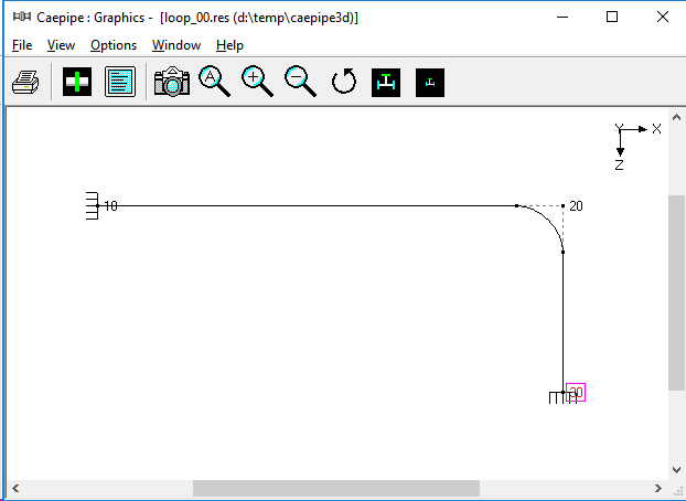
DATA: An 8" NB Schedule 80 pipe (see Fig. 1A) connects two equipment at nodes 10 and 30 with an offset of 4' (i.e., equal to distance between nodes 20 and 30). The pipe, made of A53 Grade A carbon steel, is heated to 300 deg.F.
This problem illustrates the use of expansion loops to reduce thermal stresses.
Figure 1A - Layout
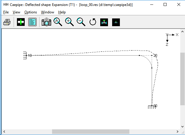
After modeling this layout in CAEPIPE, upon analysis, you will find that the pipe between nodes 10 and 20 grows thermally to the right towards node 20, while pipe between nodes 30 and 20 grows up towards node 20, as illustrated in Fig. 1B.
Figure 1B - Thermal Deflection
This thermal deformation generates large thermal stresses (orange and red zones) in the bend at node 20 and at anchor node 30, as shown in Fig. 1C.
Figure 1C - Non code-compliant (notice the reds)
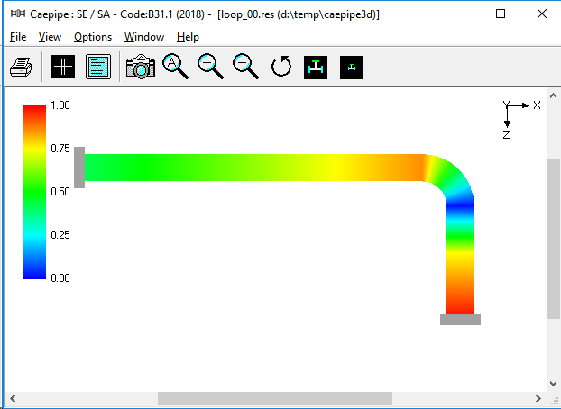
The reds illustrate that the expansion stress is over the allowables, and fails code compliance. This layout will have to be rerouted. Let us try the rerouting as shown in Fig.1D.
Figure 1D - Rerouting
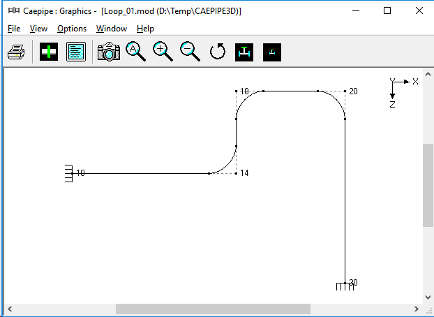
Fig. 1D shows a revised layout with a loop, introducing two additional bends at nodes 14 and 18, thereby making the layout more flexible. So, thermal growth of X-directional pipes between nodes 10 and 14 and then between 18 and 20 as well as the growth of Z-directional pipe between nodes 30 and 20 are absorbed by the three bends at nodes 14, 18 and 20, as seen in Fig. 1E. The corresponding stress contour plots for thermal and sustained load cases are shown in Fig.1F and Fig. 1G, confirming code compliance.
Figure 1E - Thermal Deformation Plot for Revised Layout
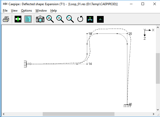
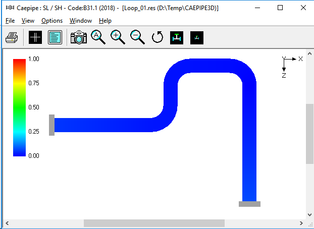
Figure 1F - Code-compliant thermal case
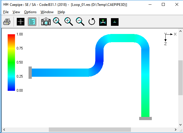
Figure 1G - Code-compliant sustained case
Example 2 - Splitting Thermal Growth
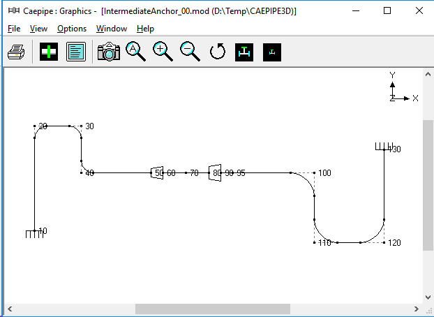
DATA: This system shown in Fig. 2A is made of three pipe sizes:
- 4" NB/Sch. 40: Between nodes 10 and the first reducer
- 6" NB/Sch. 40: Between the first reducer and the second reducer and ending at node 90
- 8" NB/Sch. 40: Between nodes 90 and anchor node 130
- T = 470 deg.F
Figure 2A - Layout
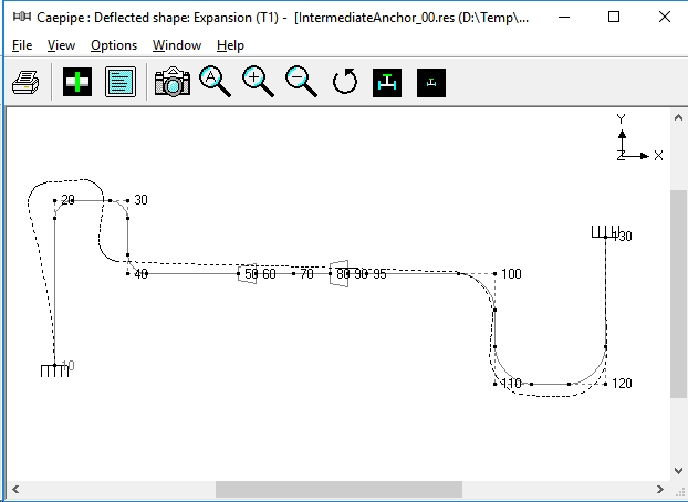
Since the loop between nodes 10 and 40 is much more flexible (4" pipe) than the loop between nodes 100 and 130 (8" pipe), the straight pipe between nodes 40 and 100 will thermally grow mostly towards the 4" loop, as shown in Fig. 2B, straining the pipe between nodes 10 and 40.
Figure 2B - Thermal Deformation Plot
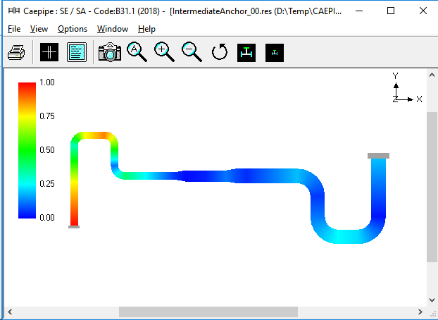
This, in turn, produces large thermal stresses (i.e., orange and red zones) in the 4" loop and at anchor node 10, as observed in Fig. 2C. In other words, the thermal growth of pipe between nodes 40 and 100 is mostly absorbed by the 4" loop and very little by the 8" loop, defeating the very purpose of the 8" loop.
Figure 2C - Thermal Stress Contour Plot
In order to alleviate thermal stresses in the 4" loop, introduce an intermediate anchor at node 95 immediately after the second reducer, so that the thermal growth of straight pipe from node 95 to node 100 is absorbed by the 8" loop, while the thermal expansion of straight pipe between nodes 40 and 95 is absorbed by the 4" loop, thereby making both loops achieve their intended purpose. The corresponding thermal displacement and thermal stress contour plots are given in Fig. 2D and Fig. 2E respectively.
Figure 2D - Thermal Deformation Plot for Layout with Intermediate Anchor
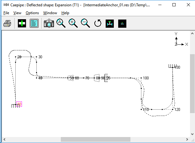
Figure 2E -Thermal Stress Contour Plot for Layout with Intermediate Anchor
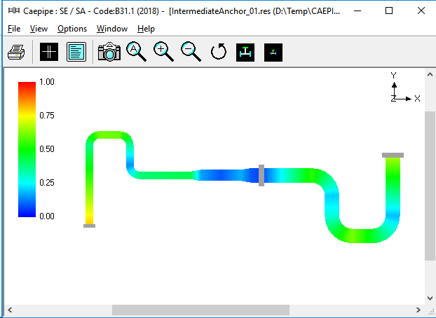
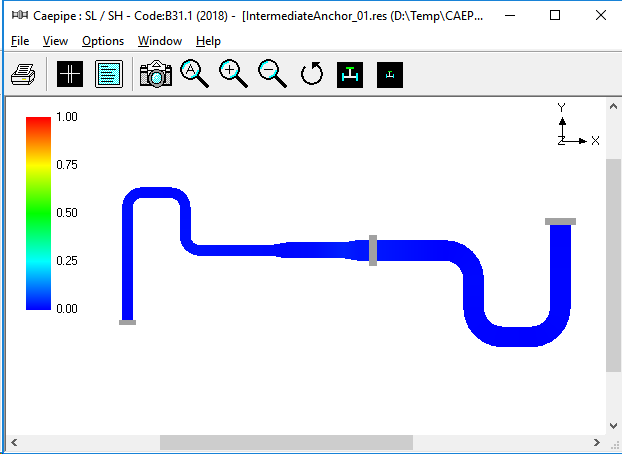
Fig. 2F confirms that the present configuration with only two equipment nozzles at nodes 10 and 130 and an intermediate anchor at node 95 safely meets the code stress requirement for sustained load.
Figure 2F - Sustained Stress Contour Plot for Layout with Intermediate Anchor
Example 3 - Axial Restraints to Direct Thermal Growth
This problem shows how axial restraints (i.e., pipe supports that prevent movement along a pipe's axis) can be effectively used to direct thermal growth towards expansion loops and split thermal growth in a line such that the two piping portions grow in opposite directions.
Figure 3A - Layout with Intermediate Anchor at Node 95
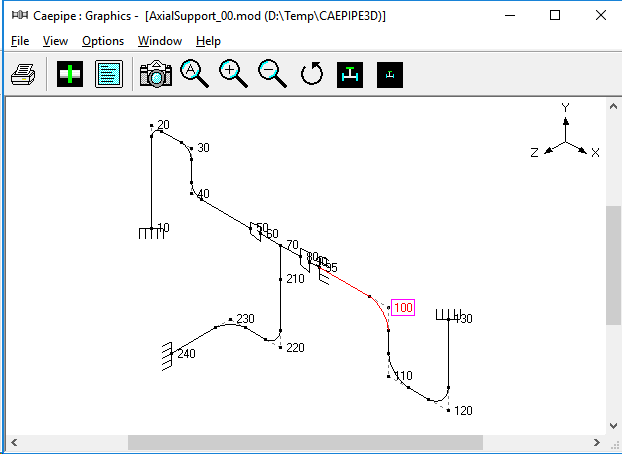
Fig. 3A shows the same problem as in Example 2 but with a 6" NB branch line added at the welding tee at node 70 (i.e., from node 70 to node 240).
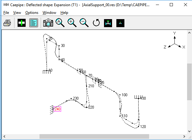
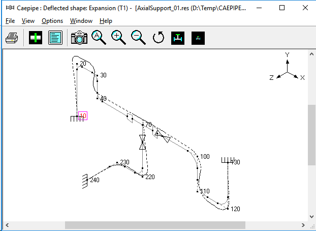
The deformed geometry due to the thermal load (Fig. 3B), shows that the tee at node 70 does not move up in +Y-direction. The intermediate anchor at node 95 restrains the vertical riser (between nodes 220 and 70) from thermally growing upward towards node 70. As a result, this riser grows downward producing large bending moments and stresses at and around equipment nozzle at node 240.
Figure 3B - Thermal Deformation Plot
Since the intermediate anchor effectively restrains upward growth of this vertical riser node 70, we see large localized thermal stress at the welding tee. See thermal stress contour plot shown in Fig. 3C.
Figure 3C - Thermal Stress Contour Plot
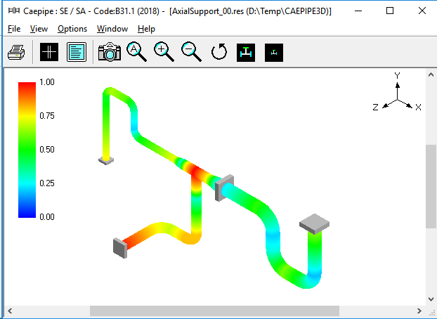
Figure 3D - Layout with Axial Restraints at Node 95 and 210
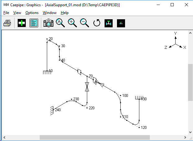
Fig. 3D shows the same piping system with one axial restraint at 95 (replacing the intermediate anchor at node 95) and another at node 210 - the one at node 95 splits and directs thermal growth towards the 4" and 8" loops and permits the horizontal line to move up in +Y-direction at node 70; the second one at node 210 splits the thermal growth of the vertical riser (between nodes 220 and 70). The resulting deformed geometry plot in Fig. 3E shows a more flexible system, which produces smaller forces and moments, and hence stresses at the equipment nozzle node 240 and welding tee node 70.
Figure 3E - Thermal Deformation Plot for Layout with Axial Restraints
Figures 3F and 3G show the thermal and sustained stress contour plots (in this case sustained stress is due to only deadweight as pressure is zero), confirming a code-compliant system for both load cases.
Figure 3F - Thermal Stress Contour Plot for Layout with Axial Restraints
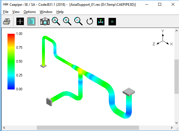
Figure 3G - Sustained Stress Contour Plot for layout With Axial Restraints
EXAMPLE 4 - Locating Supports For Deadweight Analysis
This example illustrates how to select and locate vertical supports to carry piping deadweight in the operating condition.
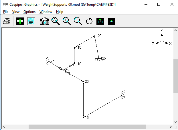
Fig. 4A shows a practical problem with 10" NB Standard schedule pipe from equipment nozzle at node 5 up to the reducer at node 30, 8" NB Standard schedule pipe from this reducer to the pump nozzle at node 40, and a 6" NB Standard schedule branch line from the welding tee at node 25 to the equipment nozzle at node 125.
Figure 4A - Layout with Node Numbers
The thermal stress contour plot given in Fig. 4B confirms that the piping system is highly flexible and hence meets the code requirement for thermal load.
Figure 4B - Thermal Stress Contour Plot
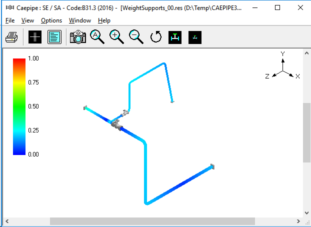
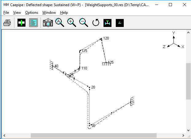
Fig. 4C shows the deflected shape for sustained load (i.e., mainly deadweight). It is observed that the weight of
i. the horizontal line from node 5 to node 15 and
ii. a major portion of the vertical riser from node 15 to node 20 is carried by the equipment nozzle at node 5. On the other hand, the pump nozzle at node 40 carries the weight of the horizontal line from node 20 to node 40,
iii. the valve portion of the branch line from node 25 to node 125 and
iv. a small portion of the vertical riser from node 15 to node 20.
Figure 4C - Sustained Load Deflected Shape
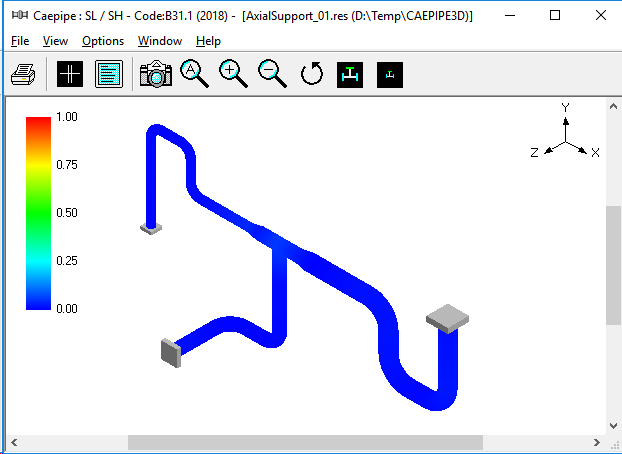
The deformation response for deadweight, in turn, generates large forces and moments and hence large sustained stresses at nozzle nodes 5 and 40 as shown in Fig. 4D for sustained stress contour plot.
Figure 4D - Sustained Stress Contour Plot
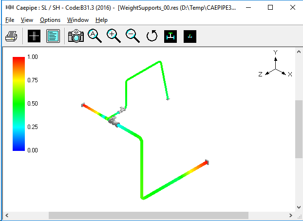
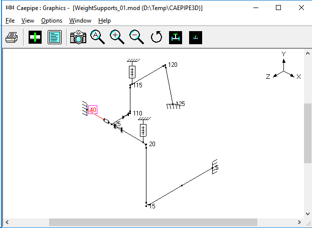
Fig. 4E shows the same layout with variable spring hangers at the bends at nodes 20 and 115, which carry piping deadweight and provide negligible restraint to thermal movement from cold to hot condition and vice versa.
Figure 4E - Layout with Hangers
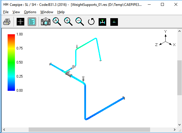
The thermal and sustained stress contour plots given in Fig. 4F and Fig. 4G confirm that the piping system with hangers is code-complaint for both sustained and thermal load cases.
Figure 4F - Thermal Stress Contour Plot for Layout with Hangers
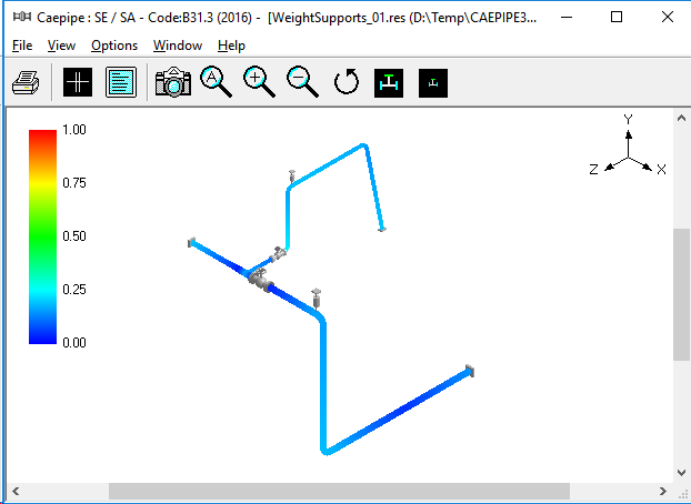
Figure 4G - Sustained Stress Contour Plot for Layout with Hangers
EXAMPLE 5 - Making Layout Changes to Reduce Thermal Stresses
This practical example illustrates how to place resting steel supports to carry the system weight with operating fluid and modify the layout in order to re-direct thermal growth to comply with code stress requirements.
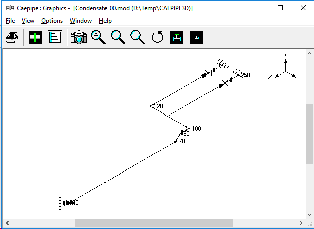
Fig. 5A shows the initial layout where condensate from a tank (node 10) is extracted by the pump suction lines. When one pump is operating, the other one is on standby.
Figure 5A - Layout with Node Numbers
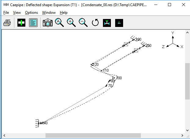
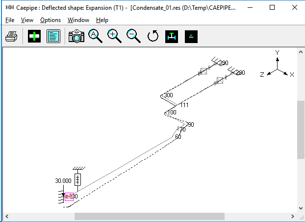
From Fig. 5B, we see that the pipeline from nodes 10 to 100 grows thermally in the -Z direction (towards the pumps), whereas the two pump suction lines, one from nodes 120 to 180 and the other from nodes 110 to 250, grows in the opposite direction towards the tank (+Z direction). So, the straight pipe between nodes 100 and 120 (with a welding tee at node 110) experiences two opposing deflection patterns -the pipe portion between nodes 110 and 120 is being deflected in the +Z direction like a rigid stick while the portion from nodes 10 to 100 deflects in the -Z direction.
Figure 5B - Thermal Deformation Plot
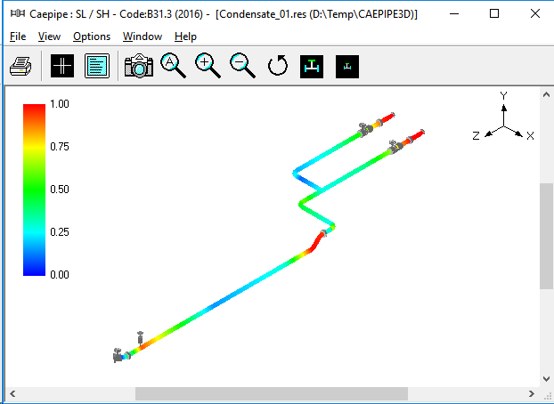
This causes the pipe between nodes 100 and 110 to bend at the tee producing high strains and hence thermal stresses locally at the tee node 110, as shown in Fig. 5C.
Figure 5C -Thermal Stress Contour Plot
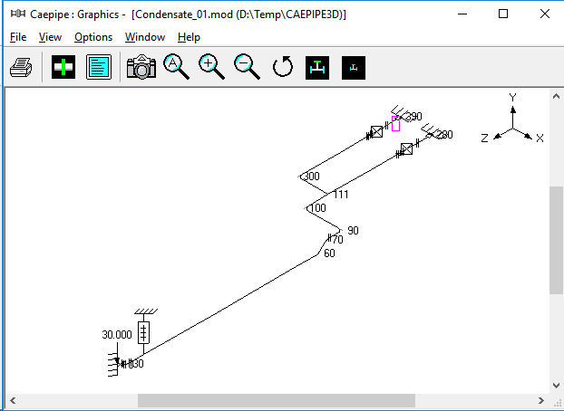
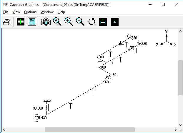
In order to reduce these thermal stresses at node 110, we cut the straight pipe between nodes 100 and 120 into two parts - one part is the pipe from nodes 100 to 110 and the second part is from nodes 111 to 410 to 300. We then shift the second part downstream towards the two pumps, resulting in the modified layout shown in Fig. 5D.
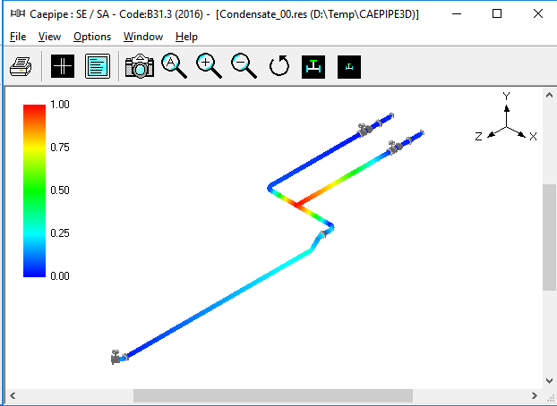
Figure 5D - Revised Layout with Node Numbers
This shift of pipe downstream does not adversely increase the pressure drop between the tank at node 10 and the class=""umps at nodes 180 and 250. From the thermal deformation plot for this revised layout shown in Fig. 5E, we can see that the two pump suction lines from the suction nozzles to the welding tee at node 111 have almost equal thermal growth in the +Z direction.
Figure 5E - Thermal Deformation Plot for Revised Layout
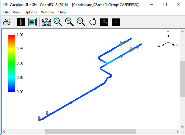
The branch pipe between nodes 111 and 300 acts as a rigid stick resulting in lower thermal stresses in that branch pipe as seen in Fig. 5F.
Figure 5F -Thermal Stress Contour Plot for Revised Layout

In addition, we see that the two pump suction lines make the bend node 100 grow thermally in the +Z direction, whereas the pipe from the tank node 10 to the bend node 90 grows in the -Z direction. These opposing deflections rotate the interconnecting pipe between nodes 90 and 100 like a (horizontal) "see-saw" in the horizontal XZ plane, resulting in lower thermal stresses in this region, as observed in Fig. 5F.
Although the thermal stress criterion has been met, the weight stresses exceed the sustained stress allowables, as illustrated by many red and orange areas in the sustained stress contour plot given in Fig 5G.
Figure 5G - Sustained Stress Contour Plot for Revised Layout
This is because there are no vertical supports (excluding the three nozzles and a variable spring hanger at node 52) to carry the weight of the system. Vertical resting supports are therefore introduced as shown in Fig. 5H.
Figure 5H - Revised Layout with Resting Supports
The recalculated sustained stress (i.e., weight + pressure) contour plot (with most areas in blue) shown in Fig. 5J are now well below the allowable stress values, and hence code-compliant.
Figure 5J - Sustained Stress Contour Plot for Rested layout with Resting Supports
This concludes our tutorial on the basics of pipe stress analysis. We hope you feel confident now in "playing" with CAEPIPE by creating simple models and conducting several "what-if" studies on them, as alluded to in the examples above.
If you have questions, please feel free to send them to us (support@sstusa.com). If you have not downloaded the free pipe stress analysis software, visit www.sstusa.com.