Tutorial for Soil Modeling for Buried Piping using CAEPIPE
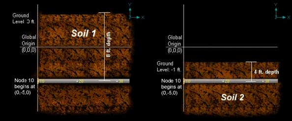
Ground level for soil in CAEPIPE is the height of the soil surface from the global origin (height could be positive or negative). It is NOT a measure of the depth of the pipe’s centerline.
In the figure below, the height of the soil surface is 3 feet above the global origin. Pipe node 10 [model origin] is defined at (0,-5,0). So, the pipe is buried 8’ (3’ - [-5’]) deep into the soil. The pipe centreline is calculated by CAEPIPE from the given data
This tutorial shows different cases of Soil modelling for Buried Piping Analysis.
Case 1: Piping layout buried under same type of soil
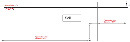
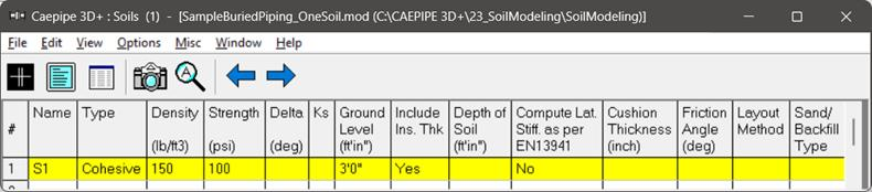
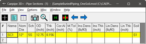
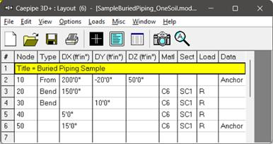
In the Figure shown above, 12” Schedule STD piping is assumed to be buried in same type of soil throughout. To represent the case shown above, you need to define in CAEPIPE, a section card “SC1” and a soil “S1” with its properties and Ground Level as +3’0”. After defining the property of soil, tie soil “S1” defined with the section “SC1” for the stress layout defined using Nodes 10 through 50. When done, CAEPIPE will automatically compute the depth of soil above Nodes 10 and 20 as 23’0” [= +3’0” - (-20’0”)]. Similarly, for Nodes 30, 40 and 50, the depth of soil will be internally computed as 13’0” [= +3’0” - (-10’0”)]. See the model SampleBuriedPiping_OneSoil.mod for details.
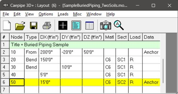
Case 2: Piping Layout buried under different type of soils
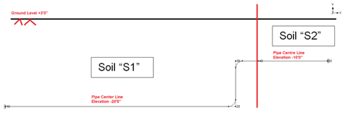
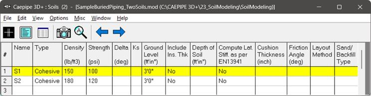
In the Figure shown above, 12” Schedule STD piping is assumed to be buried under two type of soils “S1” and “S2” with Ground level as +3’0”.
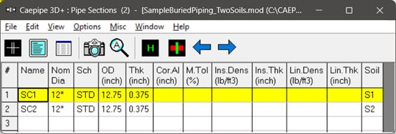
To represent this case, you need to define two section cards say “SC1” and “SC2” with their Nominal size as 12” and Schedule as “STD”. Following this, define two soils “S1” and “S2” with their required properties and Ground level as +3’0”. After defining the soils, tie the soil “S1” with “SC1” and “S2” with “SC2”. Then in the layout define the Section as “SC1” for Elements from Node 10 through Node 40 and define the Section as “SC2” for Element between Node 40 and 50. When done, CAEPIPE will automatically compute the depth of soil above Nodes 10 through 50 as explained in Case 1.
See the model SampleBuriedPiping_TwoSoils.mod for details.
Case 3: Depth of soil above pipe centre lines are varying for the stress layout
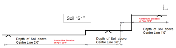
In the Figure shown above, 12” Schedule STD piping is assumed to be buried under same type of soil with depth of soil above centre line is varying for the stress layout as given above.
To represent this scenario in CAEPIPE follow the steps given below.
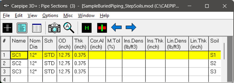
1. Define three (3) section cards “SC1”, “SC2” and “SC3” with same Nominal Size as 12” and Schedule as STD.
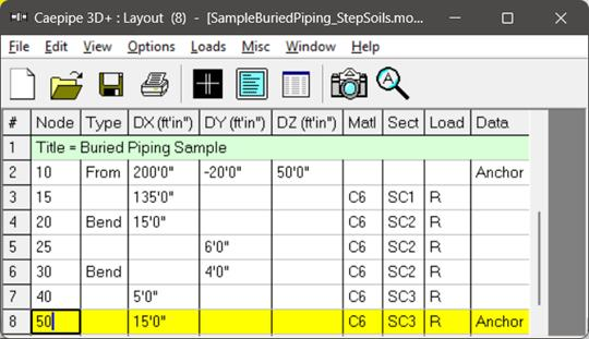
2. Generate the layout as shown in the attached model “SampleBuriedPiping_StepSoils.mod”.
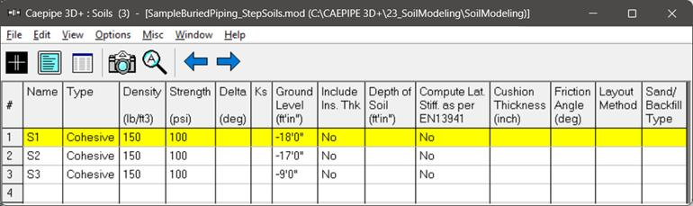
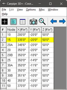
3. From the Coordinate list of CAEPIPE (can be seen through Layout Window > View > List > Coordinate), calculate the Ground Level for Nodes 10 and 15. For this example, Ground Level is -18’0” (= Y Coordinate for Node 10 + Soil Depth = -20’0” + 2’0”).
4. Follow Step 3 and calculate the Ground Levels above Nodes 20 and 40. For this example, it is -17’0” and -9’0” respectively.
5. Define three (3) soils “S1”, “S2” and “S3” with Ground Levels as -18’0”, -17’0” and -9’0” respectively and associate “S1” with “SC1”, “S2” with “SC2” and “S3” with “SC3” as shown in the attached model “SampleBuriedPiping_StepSoils.mod”.
6. Save the model and perform the analysis.
Case 4: Sloped line with uniform depth of Soil above Pipe Centre line
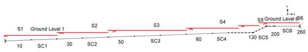
In the Figure below, 12” Schedule STD sloped line is assumed to be buried under same type of soil with depth of soil above centre line as 2’ throughout the stress layout. Being a sloped line, we need to define a number of soils by changing its ground level to best simulate the field condition. In the example shown below, the stress layout is covered with six ground levels.
To represent the scenario shown above in CAEPIPE follow the steps given below.
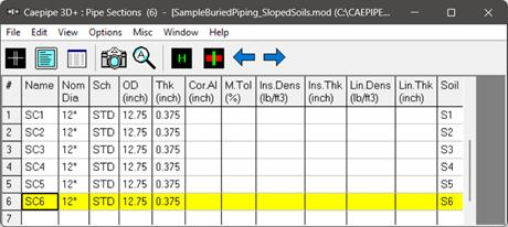
1. Define six (6) section cards “SC1” through “SC6” with same Nominal Size as 12” and Schedule as STD.
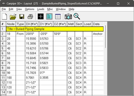
2. Create the stress layout by defining DX, DY and DZ of each Node from Node 10 through Node 260.
3. From the Coordinate list of CAEPIPE (can be seen through Layout Window > View > List > Coordinate), calculate the Ground Level for Nodes 30, 50, 80, 130, 200 and 260. For example, add 2’ to the Y coordinate of Node 30 to find its Ground Level.
4. Follow Step 3 and calculate the Ground Levels at Nodes 50, 80, 130, 200 and 260.
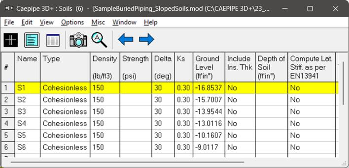
5. Define six (6) soils “S1” through “S6” corresponding to Nodes 30, 50, 80, 130, 200 and 260 with their Ground Levels entered as computed.
6. Associate Soils “S1” through “S6” to “SC1” through “SC6”. Save the model and perform the analysis. See the attached model “SampleBuriedPiping_SlopedSoils.mod” for details.
For complex stress layout that runs on sloped terrain with uniform Depth of soil above pipe centre line, the procedure given above may become laborious at this time.
For all the Cases given above, CAEPIPE will compute internally the Soil stiffnesses in three directions (axial, transverse and vertical) and apply them ONLY at node points defined in the stress layout. For further details, see the Section titled “Buried Piping” in CAEPIPE Technical Reference manual. This manual and other three (3) manuals of CAEPIPE can be accessed from the link www.sstusa.com/caepipe-docs.php.
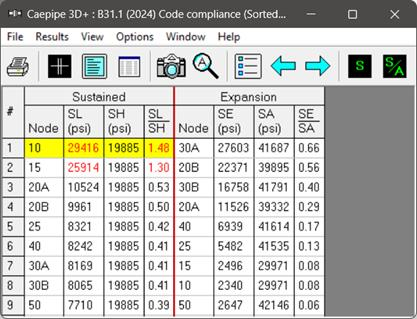
As an example, from the sorted stress results for model “SampleBuriedPiping_StepSoils.mod”, you will observe that the piping is overstressed in Sustained load case as CAEPIPE applies the soil stiffnesses in three directions only at nodes defined in the stress model.
So, it is important that you should discretize the long section of the straight pipe manually into smaller lengths to best simulate soil to pipe interaction by following the procedure given in Buried Piping Tutorial. Long straight pipe sections can be discretized automatically using the command “Layout Window > Edit > Refine Nodal Mesh.
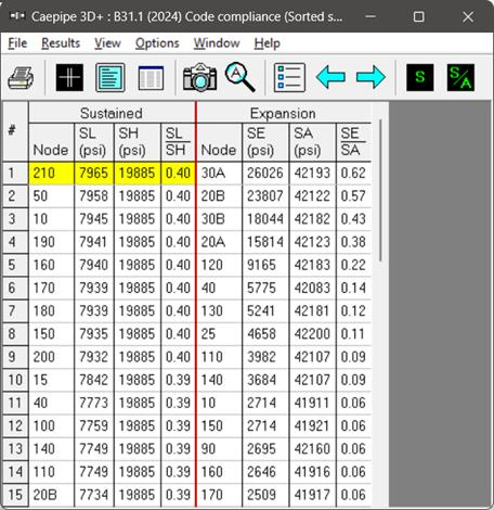
By discretizing the long pipe sections into smaller lengths for model “SampleBuriedPiping_StepSoils.mod” by following the procedure given in Buried Piping tutorial, you will observe that the over stresses for Sustained case is resolved. See the model “SampleBuriedPiping_StepSoils_refined.mod” for details.
Lastly, using the “Soil restraints” results of CAEPIPE (can be seen through “Results Window > Results > Results…”) you can view the Stiffness and Loads of all the elements that are buried in soil(s).