Tutorial for Modeling Braided Flex hose using CAEPIPE
General
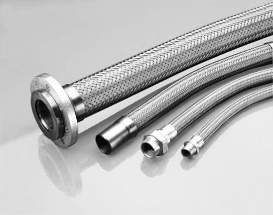
Braided Flex hose is generally used in high-pressure and high-velocity applications to eliminate vibrations that otherwise could cause damaging effects to surrounding components. Braided Hose in general has the following properties.
In Axial tension, flex hose has stiffness, but many orders of magnitude less than that of a steel pipe with the same Nominal size.
· In Axial compression, flex hose is highly flexible and can be considered as “Free”.
· In Lateral translations, flex hose is highly flexible and can be considered as “Free”.
· In the two bending rotations, the flex hose is highly flexible and can be considered as “Free”.
· In Torsion, however, the flex hose has stiffness but it is many orders of magnitude less than that of a steel pipe with the same Nominal size.
In order to model the Braided Flex hose, the following stiffnesses are assumed in this tutorial.
· Axial Stiffness in Compression = 1 lb/in (or low number)
· Axial Stiffness in Tension = 100 lb/in (or actual stiffness from manufacturer)
· Lateral Translational Stiffnesses = 1 lb/in (or low number)
· Bending Stiffnesses = 1 lb-in/deg (or low number)
· Torsional Stiffness = 1E+05 in-lb/deg (or actual stiffness from manufacturer)
Using the above data, Braided Flex hose can be modeled in two ways as detailed below.
Option 1: As a combination of a Bellow and a Tie Rod (Recommended)
Step 1:
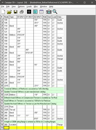
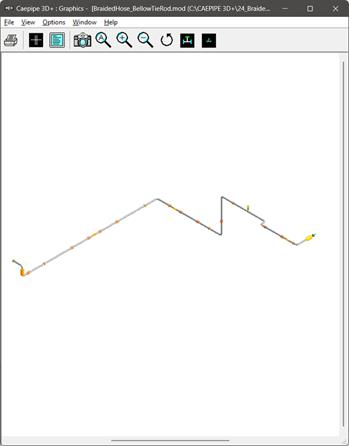
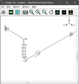
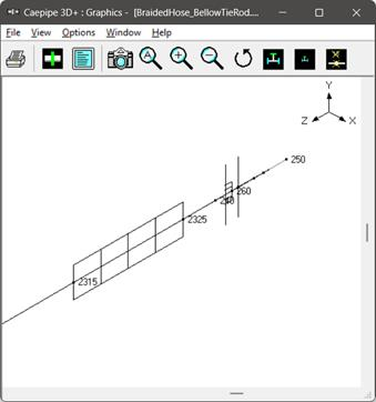
In the CAEPIPE model shown below, Flex hose is modeled as a combination of a Bellow and a Tie Rod between Nodes 30 and 31 as well as between Nodes 2315 and 2325.
Step 2:
As mentioned above under the Section titled “General”, enter the stiffness of Bellows between Nodes 30 and 31 as well as between Nodes 2315 and 2325 as follows.
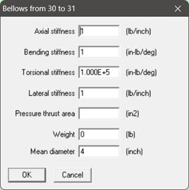
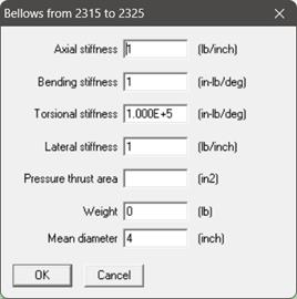
Note: Stiffness values should always be non-zero. In addition, for Flex hose, Pressure Thrust area should be entered as 0.0 or left blank.
Step 3:
Different Axial Stiffness in Compression and Tension of a Flex hose can be modeled using Tie Rod in CAEPIPE. Tie rod is a nonlinear element that allows user to enter different stiffnesses and gaps in tension and compression.
When the computed displacement at a Tie Rod node is greater than the tension gap specified, then tension stiffness entered is used in analysis. On the other hand, if the displacement is less than the tension gap, then zero stiffness is used in analysis.
Similarly, when the computed displacement at a Tie Rod node is greater than the compression gap specified, then compression stiffness entered is used in analysis. On the other hand, if the displacement is less than the compression gap, then zero stiffness is used in analysis.
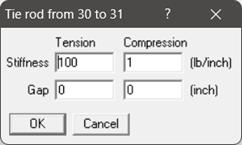
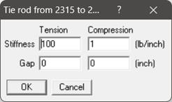
In this tutorial, since the Gaps in Tension and Compression are “0”, CAEPIPE will automatically use the Tension Stiffness as “100 lb/in” and Compression Stiffness as “1 lb/in” in analysis.
Step 4:
Complete the piping layout, save the model and perform the analysis.
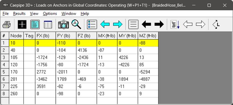
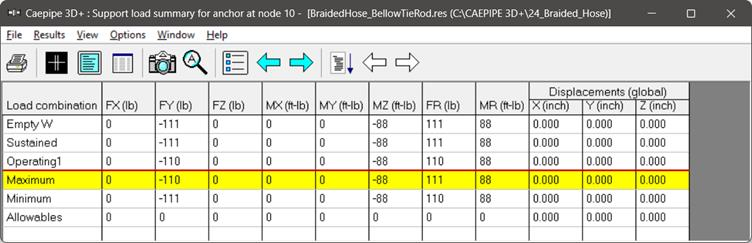
From the Support Load Summary results for Anchors at Node 10 and Node 260, you will observe that the Forces & Moments for different load cases at these anchors (located close to Flex hoses) are low.
For details, see CAEPIPE model file BraidedHose_BellowTieRod.mod and its Results file BraidedHose_BellowTieRod.res.

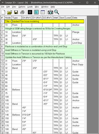
Option 2: As a combination of Anchor and Axial Limit Stop
At the connection node between the steel pipe and flex hose, the restraining effects coming from the flex hose onto the pipe are simulated using a combination of an “Anchor” and “Axial” Limit Stop at the same node.
Step 1:
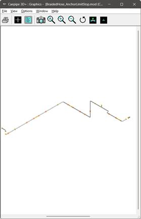
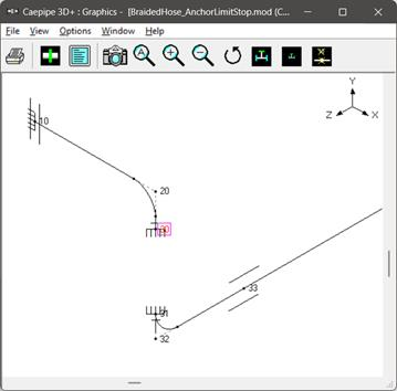
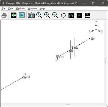
In the CAEPIPE model shown above, Flex hose is modeled as a combination of Anchor and a Limit Stop at Nodes 30, 31, 2315 and 2325 as shown below.
Step 2:
As mentioned above under the Section titled “General”, enter the stiffnesses of Anchor at Nodes 30, 31, 2315 and 2315 as given below.
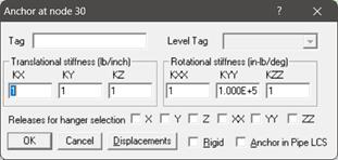
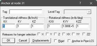
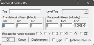

Note: Stiffness values should always be non-zero.
Step 3:
Axial Stiffness of Flex hose in Tension is modeled using Axial Limit Stop at Nodes 30, 31, 2315 and 2325 as shown below.
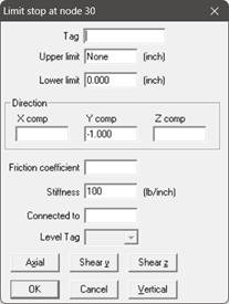

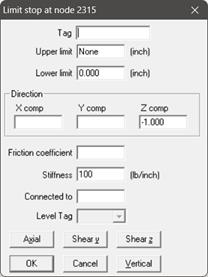
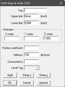
A limit stop in CAEPIPE prevents a node from moving beyond a certain distance (called a gap or a limit) in a certain direction. The node can move freely within the gap. After the gap closes, a limit stop acts as a rigid or flexible restraint (depending on your input for stiffness) resisting further movement of the node in the specified direction. If friction is specified, after the limit is reached, the friction force will oppose movement in the plane normal to the limit stop direction.
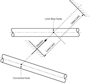
Direction of the vector normal to the plane of a Limit Stop should be specified in terms of its global X, Y and Z components. For example, if the pipe is allowed to move freely upward in +Y direction but restrained in –Y direction (a resting support), then the Direction vector should be defined as X = 0; Y = 1 and Z = 0.
Also called gaps, these limits, upper and lower, are the gaps present on either side of the node. The gap in front of the node in the positive direction of the vector is called the upper limit, and the gap to the rear of the node in the negative direction of the vector is called the lower limit. The gap is measured from the un-deflected position of the piping node.
Typically, the upper limit is positive and the lower limit is negative. In some situations, it is possible to have a positive lower limit or a negative upper limit, which is the same as forcefully displacing the node in that direction by the gap specified.
For further details on Limit Stop, see Section titled “Limit Stop” from CAEPIPE Technical Reference Manual. This manual and other manuals of CAEPIPE can be downloaded from the link www.sstusa.com/caepipe-docs.php.
Step 4:
Complete the piping layout, save the model and perform the analysis.
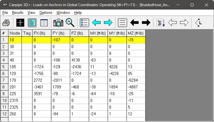
From the Support Load Summary results for Anchors at Node 10 and Node 260, you will observe that the Forces & Moments for different load cases at these anchors (located close to Flex hoses) are low.
For details, see CAEPIPE model file BraidedHose_AnchorLimitStop.mod and its results file BraidedHose_AnchorLimitStop.res.


Summary
From the Support Loads at Anchors in Operating Load case shown below for Option 1 and Option 2, it is to be noted that the forces and moments are low at Nodes 10 and 260 effectively confirming that the Flex hose are active.
In addition, the forces and moments at all other Anchors compare well between the two models confirming that either method of modeling the Flex hose is valid.