Tutorial for Thermoplastic Piping Analysis as per ASME NM.1 using CAEPIPE
General
Plastic piping has gained wide acceptance in many industries due to its lightweight, superior corrosion resistance, moderate temperature capabilities and mechanical strength. Several manufacturers produce different types of plastic pipes and fittings and provide technical assistance to their customers from design through installation.
Thermoplastic piping systems can be modeled and analyzed using CAEPIPE.
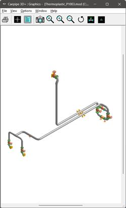
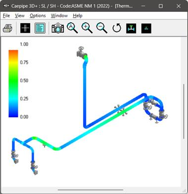
Snapshot shown below is a sample model for Thermoplastic Piping Analysis. Dimensions of the fittings used in this tutorial are only for representation and do not reflect the actual dimensions of Plastic Fittings. Weight of Valves and Flanges are approximated and input just to represent the Plastic Valves and Flanges available.
Step 1:
Select the Piping Code for Analysis as “ASME NM.1” through Layout Window > Options > Analysis > Code.
When done, define the material properties required for piping system through Layout window > Misc > Materials. In the Material List window shown on the screen, double click on an empty row to input a new material or double click on a material description to edit the material properties already input.
Step 2:
ASME NM.3.3 provides tables and data sheets for allowable stresses, mechanical properties (e.g., tensile and yield strength), and physical properties (e.g., coefficient of thermal expansion and modulus of elasticity) for nonmetallic materials such as chlorinated polyvinyl chloride (CPVC); polyvinyl chloride (PVC), polyvinylidene fluoride (PVDF), etc.
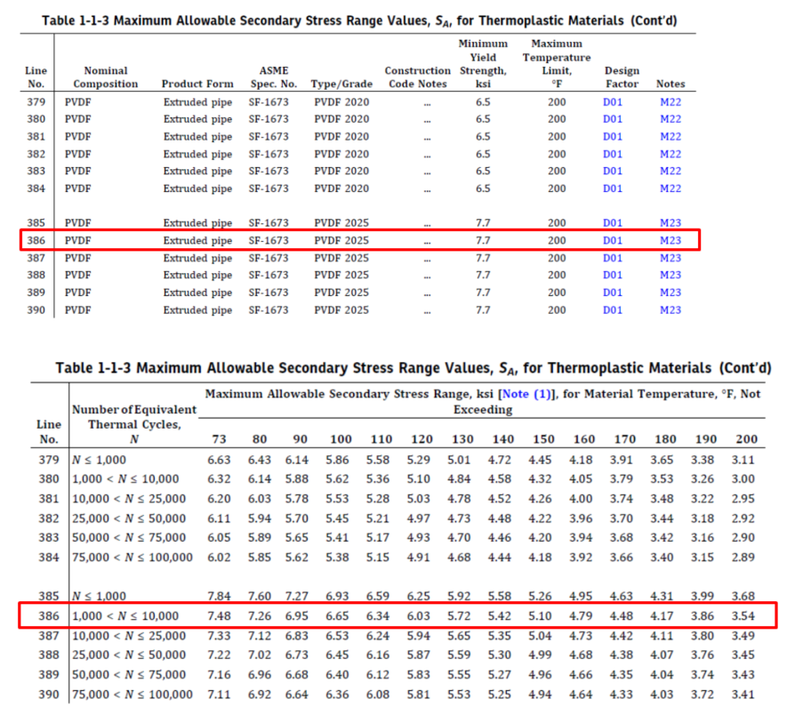
In this tutorial, material properties corresponding to PVDF Extruded pipe SF-1673 Grade 2025 (highlighted in RED below) have been referred from ASME NM.3.3 as this material has better corrosion resistance, higher yield and temperature capabilities compared to other Thermoplastics. The material properties thus obtained are entered into CAEPIPE material properties dialog as shown below.
Allowable stress values “Sh” and “SA” in CAEPIPE material properties are entered by referring to Table 1-1-1 for S and Table 1-1-3 for “SA“ respectively for PVDF material highlighted in RED below from ASME NM.3.3. From the snapshots shown below, you will observe that the Allowable Secondary Stress Range (SA) values vary based on the number of equivalent thermal cycles and temperatures. Hence, for this tutorial, the number of equivalent thermal cycles is assumed to be 7000 (= 2 cycles / day * 350 days approx. in a year x 10 years) to obtain the value of “SA”.
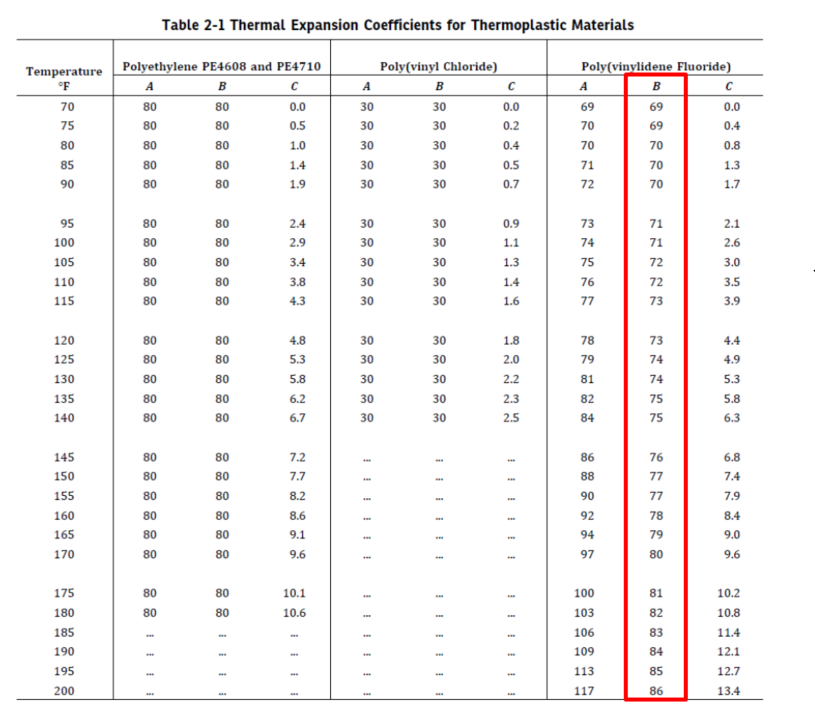

Mean Coefficient of Thermal Expansion data for PVDF material is referred from Table 2-1 corresponding to Column B (highlighted in RED above) for different temperature values and entered into CAEPIPE material properties dialog.
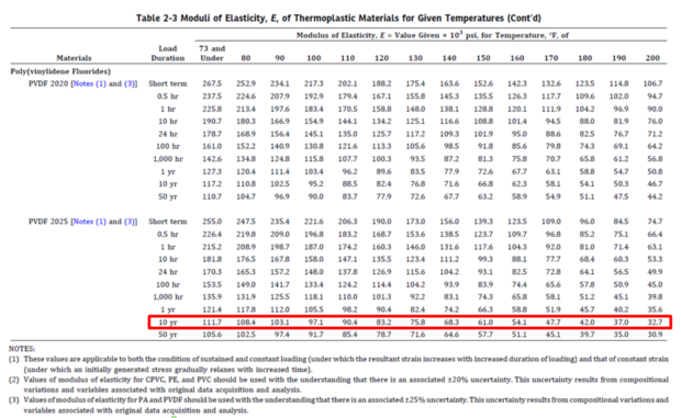
Elastic modulus data for PVDF material is referred from Table 2-3 corresponding to 10 Year (highlighted in RED above) for different temperature values and entered into CAEPIPE material properties dialog.
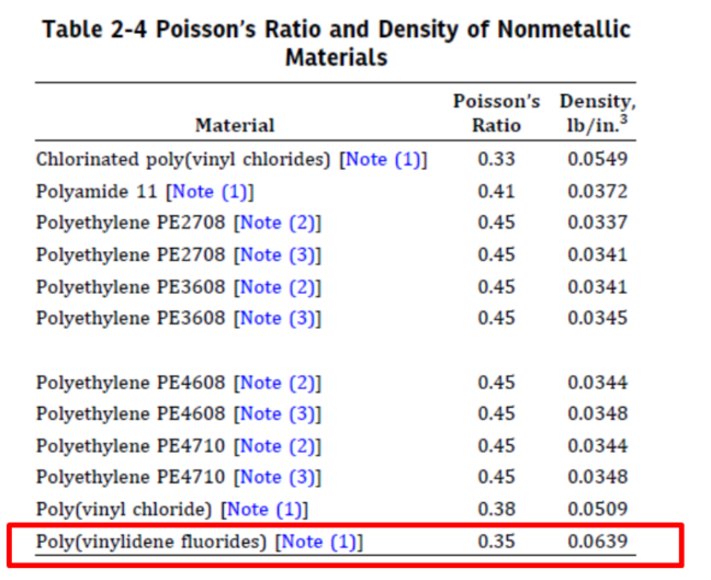
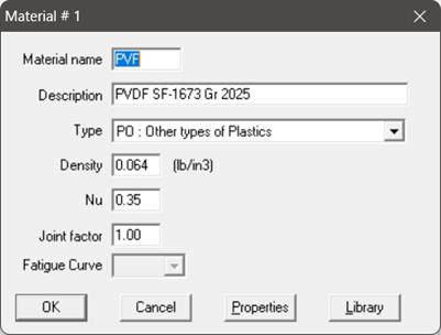
The material name can be up to five alpha-numeric characters. Enter Material name, Description, Density and Poisson’s ratio (Nu) as shown below. Select the type as “PO: Other types of Plastics” from the Type drop-down combo box and press OK.
Input the Temperature related properties into CAEPIPE material properties as shown below by referring to the material properties data given above.
Step 3:
ASME NM.3.1 provides Thermoplastic Material Specifications such as Outside Diameter, Wall Thickness, etc. for different Thermoplastic Materials. See snapshots given below for PVDF materials.
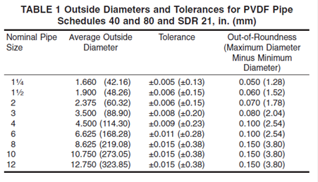
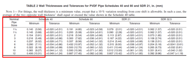
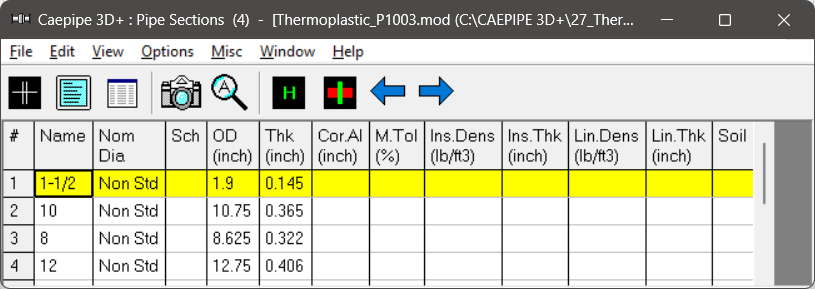
For this tutorial, Section properties such as Outside Diameter and Wall Thicknesses for various Nominal sizes are referred from Table 1 and Table 2 corresponding to PVDF material from ASME NM.3.1 (see the snapshots provided above) and entered into CAEPIPE through Layout Window > Misc > Sections (see the snapshot below).
Step 4:
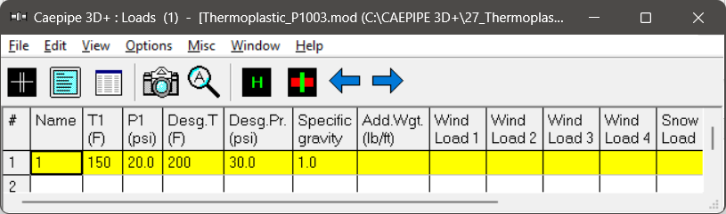
The Operating Temperature (T1), Operating Pressure (P1), Design Temperature (Desg. T) and Design Pressure (Desg. Pr) for the stress analysis are entered as shown below.
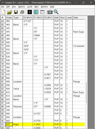
After defining the Material properties, Section properties and Loads required for the stress analysis, complete the stress layout. Save the model and Analyze through Layout window > File > Analyze. Refer to the CAEPIPE model file “Thermoplastic_P1003.mod” included with this tutorial for further details on the layout.
Step 5:
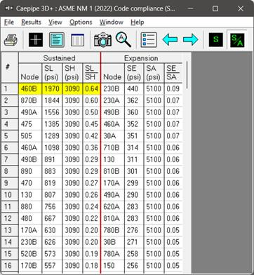
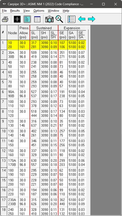
Upon successful analysis, CAEPIPE shows the code compliance as per ASME NM.1 under Sorted stresses and Code Compliance results as shown below.
Step 6:
Code Compliance results of CAEPIPE displays the stresses on an element-by-element basis. For the tutorial problem, a snapshot of Code Compliance results is shown below, in which the first element from node 10 to node 20 is highlighted. You will observe that the 2nd Column titled “Press. Allow” output the following for each element.
1. First row outputs the “Design Pressure” input for that element.
2. Second row outputs the “Calculated Allowable Pressure” for that element as per the equation provided in ASME NM.1. Please note, when the “Design Pressure” input for an element exceeds the “Allowable Pressure” computed for that element, then CAEPIPE will change the display color of Design Pressure to RED.
Step 7:
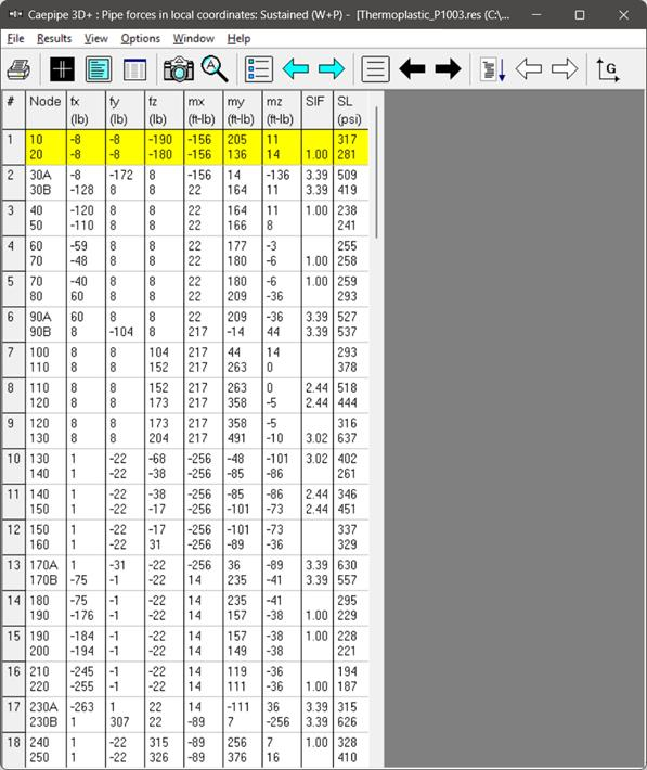
Element forces results for each load case (such as Sustained, Expansion, etc.) shows the Element forces and moments in local coordinate system along with Stress Intensification Factors (SIFs) and Stresses computed as per ASME NM.1 for each element as shown below.
Step 8:
Support Loads and Displacements for each load case can be seen through Support Loads and Displacements results of CAEPIPE respectively. For the design of supports, Support Load Summary of CAEPIPE will show the loads on each support for all load cases selected for analysis.
Note:
Refer to Section titled “ASME NM.1” in CAEPIPE Code Compliance Manual of CAEPIPE for details on how CAEPIPE computes the Flexibility Factors, Stress Intensification Factors and Code Stresses as per ASME NM.1.