Tutorial for District Heating Piping as per EN 13941-1 (2019) using CAEPIPE
The European code EN13941-1 (2019) specifies requirements for design, calculation and installation of factory made thermal insulated bonded piping systems for directly buried hot water networks for continuous operation with treated hot water at various temperatures up to 120 deg. C and occasionally with peak temperatures up to 140 deg. C and maximum internal pressure of 2.5 MPa.
This tutorial provides guidelines and step-by-step procedure for performing buried piping analysis and EN13941-1 code compliance using CAEPIPE for Single bonded district heating pipes.
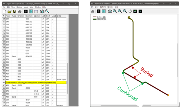
The piping model developed for this tutorial is shown below. This pipeline is partially below ground with expansion cushions at the buried bends.
Step 1:
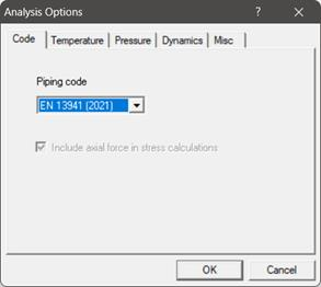
As the requirements for Analysis of buried, bonded heating pipes as per EN13941-1 are very different from those for other piping codes, it is important to set this code as piping code for analysis before the stress layout is developed. This will enable CAEPIPE to check and validate the data entered at different stages of the stress layout for buried, single bonded district heating pipes.
This analysis code can be selected through CAEPIPE Layout Window > Options > Analysis > Code > EN13941 (2019) as shown below.
Step 2:
Define the properties of soils along with expansion cushion. Soils with and without expansion cushion can be defined through CAEPIPE Layout Window > Misc > Soils.
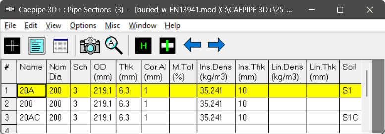
The snapshot shown below provides properties of two (2) soils. Soil S1 without expansion cushion and soil S1C with expansion cushion.
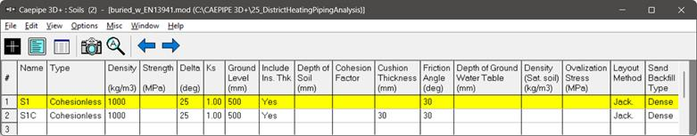
Two types of soils can be defined - Cohesive and Cohesionless.
Cohesive soil is hard to break up when dry, and exhibits significant cohesion when submerged. Cohesive soils include clayey silt, sandy clay, silty clay, clay and organic clay.
Cohesionless soil is any free-running type of soil, such as sand or gravel, whose strength depends on friction between particles.
Soil density and Ground level are input for both cohesive and cohesionless soils. The Ground level is used to calculate depth of the buried section. For cohesive soil, Strength is the un-drained cohesive strength (Cs). For cohesionless soil, Delta is angle of friction between soil and pipe, and Ks is Coefficient of horizontal soil stress.
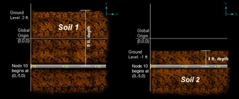
Ground Level
Ground level for a soil is the height of the soil surface from the global origin (height could be positive or negative). It is NOT a measure of the depth of the pipe’s centerline.
For example, in the figure below, the height of the soil surface for Soil 1 is 3 feet from the global origin. Pipe node 10 [model origin] is defined at (0,-5, 0). So, at Node 10, the pipe is buried 8’ [= (3’ – (-5’)] deep into the soil. Define similarly for the other soil.
The pipe centerline is calculated by CAEPIPE from the given data.
Depth of Soil above Pipe’s Centerline
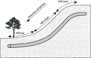
When the option “Value entered is Depth of Soil above pipe centerline” is turned ON in Soil input, then CAEPIPE will compute maximum soil loads for the sections buried using the Depth entered. This option will be helpful for modeling pipes that are running up or down a hill with same depth of soil filled above pipe’s centerline as shown in the figure given below.
Warning:
Assign Soil only to those elements that are really buried in soil when the option “Value entered is Depth of Soil above pipe centerline” is turned ON.


For further details on other input parameters, refer to CAEPIPE Technical Reference Manual. For details on calculation of soil restraints, refer to CAEPIPE Code Compliance Manual.
Step 3:
Tie the soils defined above with pipe sections through Layout window > Misc > Sections or Ctrl+Shft+S (to list Sections). Double click on the required section property. You will see the field Soil in the bottom right corner. Pick the soil name from the drop-down combo box.
If a part of a piping system uses a certain pipe section with some portion of it buried and the balance not buried, then two separate pipe sections have to be defined, with one of them without soil and the other with soil.
So, in the piping system used for this tutorial, two pipe sections named 20A and 20AC are defined for buried pipes without and with expansion cushion respectively. A pipe section named 200 is defined to represent above ground piping model. All three pipe sections have insulation as shown below.
Step 4:
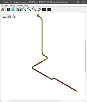
Review the stress layout by highlighting the buried sections of the model in graphics. If your model contains sections that are above ground and buried, then you can selectively see only the buried sections of piping in CAEPIPE graphics by highlighting the section that is tied to the soil. Use the Highlight feature under the Section List window and place highlight on the buried piping section (see Highlight under List window>View menu, or press Ctrl+H). The Graphics window should highlight only that portion of the model that is using that specific section with that soil.
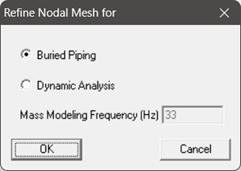
Step 5:
It is at the bends, elbows, and branch connections that the highest stresses are found in buried piping subjected to thermal expansion of the pipe. These stresses are due to the soil forces that bear against the transverse run. The stresses are proportional to the amount of soil deformation at the bend/elbow or branch connection. Hence, piping elements at the junction of bends, elbows and branch connections are to be refined in the stress layout.
This can be performed through Layout window > Edit > Refine Nodal Mesh > Buried Piping. Please see the section titled “Buried Piping” in the Technical Reference Manual for details on “Refine Nodal Mesh”.
Step 6:
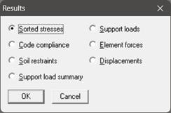
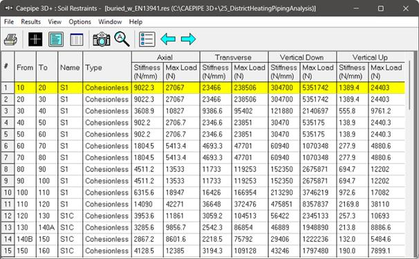
Save and analyze the model through File > Analyze. Upon analysis, under Results, CAEPIPE displays an option “Soil Restraints” in addition to other analysis results.
Step 7:
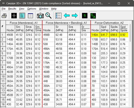
The stresses computed by CAEPIPE as per EN13941-1 (2019) are sorted in the descending order of stress ratios. This can be seen through CAEPIPE Results window > Results > Results… > Sorted stresses.
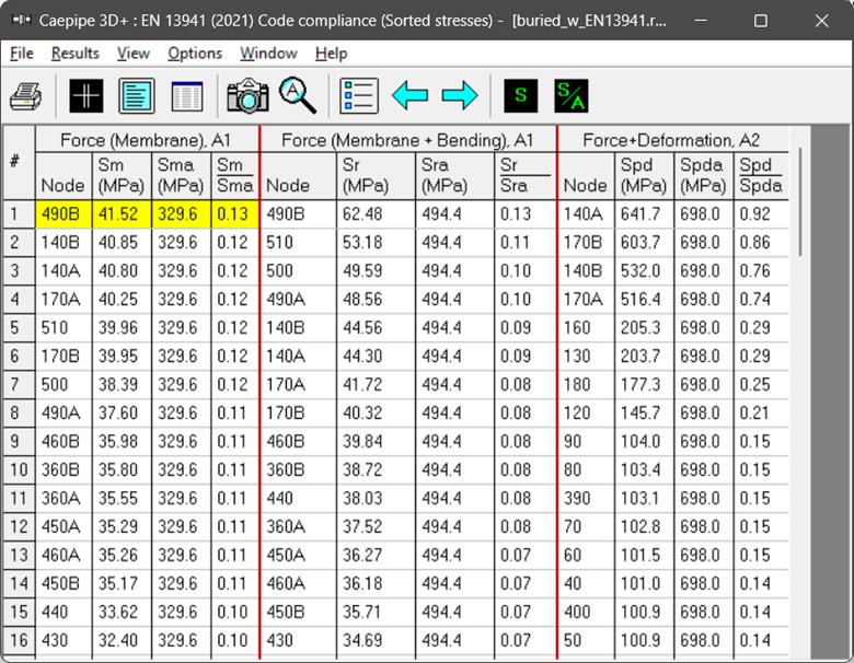
Under the Results > Element forces, the element forces in local coordinates as well as Stress Concentration Factors and Stresses computed as per EN13941-1 (2019) for each element (pipe/bend) are shown for each selected load case.

Color coded stresses may be rendered in the graphics window by pressing the Show Stress Ratio (S/A) button (or choose View > Show Stress Ratio). The stress ratios under the highlighted columns (the bar highlights the relevant column simultaneously) are displayed in the graphics window. Use the left and right arrow keys to change the highlighted columns or click in a particular column.