Tutorial on Analysis with Multiple Thermal Loads using CAEPIPE
General
The Reference Temperature (can be defined through Layout window > Options > Analysis” is “the ambient temperature at which the pipe is to be/was initially installed”. In other words, when the whole piping system is at Reference Temperature, the piping system is “stress free” and the involved pipe supports are “loads free”, as long as there are NO cold springs introduced during the installation of the system. There is no need to input Reference Pressure, as at installation the pressure is zero.
T1, T2 etc. (tuned ON through the “Layout window > Loads > Load cases”) refer to the temperatures prevailing during different operational states of the piping system. Please note that the value of T1 for the first operational state could be different for different portions of the piping system. In other words, you could input multiple values for T1 (by having at least that many “Loads”) corresponding to different portions of the piping. In addition, the same element in the piping system can experience different temperatures T1, T2, T3 etc. during different operational states.
Hence, the Expansion (T1) case in the Results lists the “Range Solution” obtained for the temperature range from Reference Temperature to T1 [i.e., (T1 – Tref)], similarly for Expansion (T2), and so on. The Expansion (T1-T2) case in the Results lists the “Range Solution” obtained for the temperature range from T1 to T2, which is internally computed as [(T1 - Tref) – (T2 – Tref)], similarly for Expansion (T1-T3) and so on.
For the operating (W+P1+T1) case, CAEPIPE considers the weight, the pressure P1 corresponding to T1 and the expansion from Tref to T1.
The following are the Steps for performing Analysis with Multiple Thermal loads in CAEPIPE.
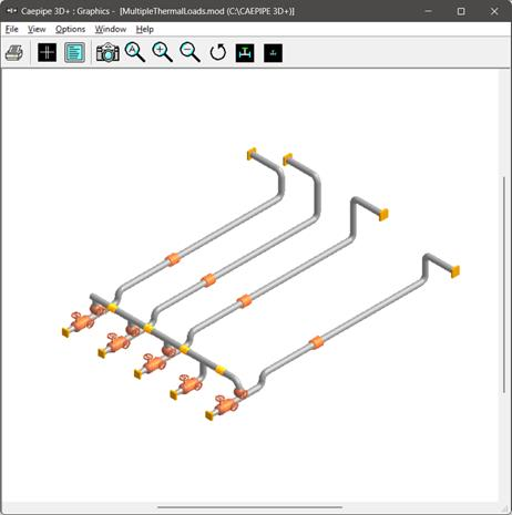
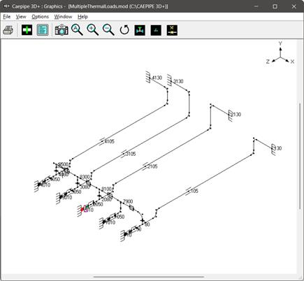
The attached stress system shows the layout of four (4) pipelines. These pipelines are connected to five (5) centrifugal pumps at one end (with one of them being the Spare) and four (4) tanks at the other end. Out of those 5 centrifugal pumps, Pump 2 is the Spare and will turn into operation when one of the other 4 pumps fails. In other words, at any point in time, 4 pumps are operating with 1 pump either on standby or not operational. To represent these, the following thermal load cases are required (see the attached model).
|
Cases
|
Description
|
|
Case 1
|
Pump 2 (the Spare) is “OFF” and the remaining Pumps are “ON”
|
|
Case 2
|
Pump 1 is “OFF” and the remaining Pumps (including Spare) are “ON”
|
|
Case 3
|
Pump 3 is “OFF” and the remaining Pumps (including Spare) are “ON”
|
|
Case 4
|
Pump 4 is “OFF” and the remaining Pumps (including Spare) are “ON”
|
|
Case 5
|
Pump 5 is “OFF” and the remaining Pumps (including Spare) are “ON”
|
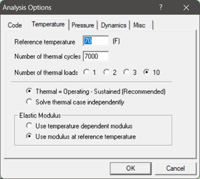
Step 1:
The above cases can be defined in CAEPIPE by defining the “Number of Thermal loads” as 10 through Layout window > Options > Analysis > Temperature.
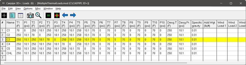
Step 2:
Define the Pressures and Temperatures for different operating cases described above through CAEPIPE Layout window > Misc > Loads. Description corresponding to Loads C1 through CHL is given in the table below for clarity.
|
Cases
|
Description
|
Pressures and Temperatures
|
|
Case 1
|
Spare Pump at Node 1010 is “OFF” and the remaining Pumps are “ON”
|
For C1, T1 = 70 degF; P1 = 0 psi. For others (C2 through C5), T1 = 250 degF and P1 = 10.1 psi
|
|
Case 2
|
Pump 1 at Node 10 is “OFF” and the remaining Pumps are “ON”
|
For C2, T2 = 70 degF; P2 = 0 psi. For others, T2 = 250 degF and P2 = 10.1 psi
|
|
Case 3
|
Pump 2 at Node 2010 is “OFF” and the remaining Pumps are “ON”
|
For C3, T3 = 70 degF; P3 = 0 psi. For others, T3 = 250 degF and P3 = 10.1 psi
|
|
Case 4
|
Pump 3 at Node 3010 is “OFF” and the remaining Pumps are “ON”
|
For C4, T4 = 70 degF; P4 = 0 psi. For others, T4 = 250 degF and P4 = 10.1 psi
|
|
Case 5
|
Pump 4 at Node 4010 is “OFF” and the remaining Pumps are “ON”
|
For C5, T5 = 70 degF; P5 = 0 psi. For others, T5 = 250 degF and P5 = 10.1 psi
|
|
Load with name “CHL” is defined to represent the portion of the piping that are always HOT irrespective of which pump is OFF. Hence, the T1 through T5 is 250 deg F and P1 through P5 is 10.1 psi.
The Load cases and Load combinations defined in the model can be seen using Layout window > Misc > Loads and Layout Window > Loads > Load cases respectively.
| ||
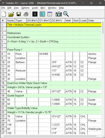
Define the loads C1 through CHL as shown in the snap shot below.
Step 3:
Assign the Loads C1 through CHL to different portions of stress system as required while creating the stress layout. After modeling the stress system, one can review the loads assigned to different portions using the Highlight feature through “Loads List window”.
From the attached model, to review the loads assigned, place the highlight on each load (C1 through CHL) and press “Ctrl+H” or select option “Highlight” under List window >View to highlight only that portion of the model that is using that specific load. The snap shot below highlight only that portion of the model that is using the Load C1.
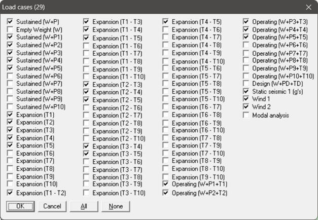
Step 4:
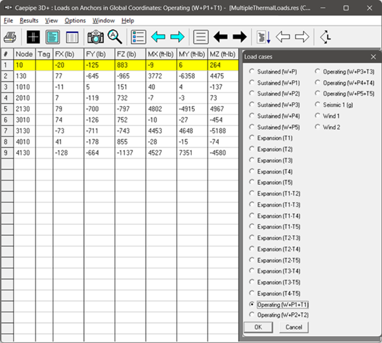
Select the load cases and load combinations required for analysis through Layout window > Loads > Load cases.
Step 5:
Save the model and perform analysis through Layout window > File > Analyze.
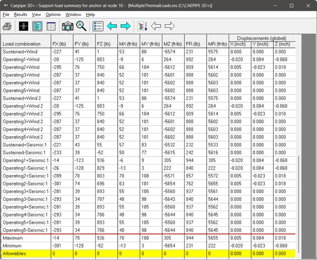
In order to understand the loads and load combinations used for analysis, review the CAEPIPE results file for Support Loads (loads acting on the supports by the piping for each load case), Element Forces & Moments (local/global forces and moments on each element for each load case) and Support Load Summary (listing support loads at particular support for all relevant load cases and load combinations).
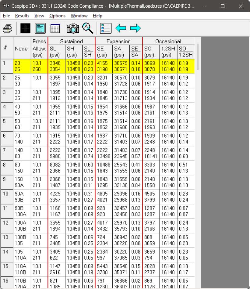
The Sorted Stresses in CAEPIPE lists the maximum of Expansion stresses for all thermal range cases at each node as well as the maximum of Sustained + Occasional stresses for all Occasional cases at each node. On the other hand, for the Sustained case, it always uses the maximum pressure among the input pressures (P1 through P10) while computing Sustained Stress at each node.
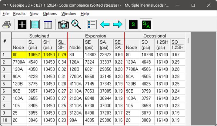
Similarly, Code Compliance report lists the Stresses element-wise following the same procedure as done for Sorted Stresses.