Tutorial on Hydrogen Pipeline Analysis as per ASME B31.12 Part PL using CAEPIPE
General
In the search for a sustainable and decarbonized future, hydrogen is emerging as a key energy carrier with tremendous potential. As the demand for hydrogen increases, the need for safe and efficient infrastructure becomes paramount. The American Society of Mechanical Engineers (ASME) recognized this need and developed the ASME B31.12 code to provide guidelines for the design, construction, and operation of hydrogen piping and pipeline systems. This comprehensive code ensures the integrity and safety of hydrogen infrastructure while promoting the growth of the hydrogen industry.
This tutorial provides steps in performing piping stress analysis of both buried and above-ground Hydrogen Pipelines as per ASME B31.12 Part PL using CAEPIPE.
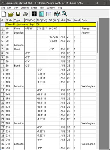
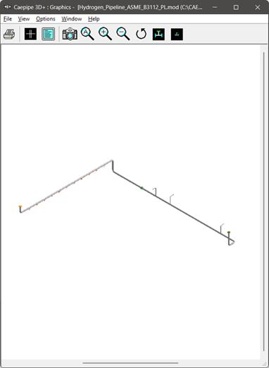
Snap shot shown below is a sample model for Hydrogen Pipelines as per ASME B31.12 Part PL where a portion of the layout is buried in soil (see the snapshot with RED highlight below) and the remaining portion of the layout is above-ground.

Step 1:
Select the piping code for analysis as “B31.12 PL” and the “Design Factor F” through Layout Window > Options > Analysis > Code as shown below and press the button “OK”. See para. PL-3.7.1 (b) for details on Design Factor F in ASME B31.12 Part PL.

Step 2:
Next define materials required for piping system through Layout window > Misc > Materials by obtaining their properties from the manufacturer or through the piping standard.
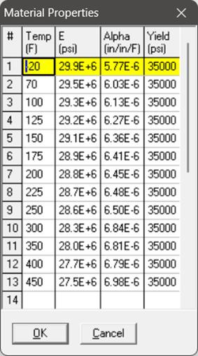
In the Material List window shown on the screen, double click on an empty row to input a new material. Enter the material properties as shown below and press the button “Ok”.

Step 3:
Click on the Properties button and input the temperature related properties as shown below.
Step 4:
Define soils properties using the command Layout window > Misc > Soils.

Two types of soils can be defined - Cohesive and Cohesionless.
Cohesive soil is hard to break up when dry, and exhibits significant cohesion when submerged. Cohesive soils include clayey silt, sandy clay, silty clay, clay and organic clay.
Cohesionless soil is any free-running type of soil, such as sand or gravel, whose strength depends on friction between particles.
Density is the density of the soil.
Strength
Soil strength. This field needs to be input only for Cohesive soil. For cohesive soil, Strength is the un-drained cohesive strength (Cs).
Ground Level
Ground level for a soil is the height of the soil surface from the global origin (height could be positive or negative). It is NOT a measure of the depth of the pipe’s centerline.
In the figure below, the height of the soil surface for Soil 1 is 3 feet from the global origin. Pipe node 10 [model origin] is defined at (0,-5, 0). So, at Node 10, the pipe is buried 8’ [= (3’ – (-5’)] deep into the soil. Define similarly for the other soil.
The pipe centerline is calculated by CAEPIPE from the given data.

Depth of Soil above Pipe’s Centerline
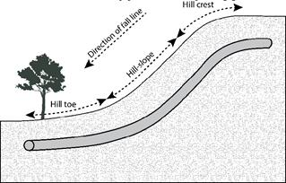
When the option “Value entered is Depth of Soil above pipe centerline” is turned ON in Soil input, then CAEPIPE will compute maximum soil loads for the sections buried using the Depth entered. This option will be helpful for modeling pipes that are running up or down a hill with the same depth of soil filled above pipe’s centerline as shown in the figure given below.
Warning:
Assign Soil only to those elements that are really buried in soil when the option “Value entered is Depth of Soil above pipe centerline” is turned ON.
Step 5:
Tie the soils defined above with pipe sections through Layout window > Misc > Sections or Ctrl+Shft+S (to list Sections). Double click on the required section property. You will see the field Soil in the bottom right corner. Pick the soil name from the drop-down combo box.

If a part of a piping system uses a certain pipe section with some portion of it buried and the balance not buried, then two separate sections have to be defined, with one of them without soil and the other with soil as shown above for Sections 2 and 2B.
Step 6:
Assign the appropriate section for each buried element on the Layout window with the correct soil around it.
Step 7:
Review the stress layout by highlighting the buried sections of the model in graphics. If your model contains sections that are above-ground and buried, then you can selectively see only the buried sections of piping in CAEPIPE graphics by highlighting the section that is tied to the soil. Use the Highlight feature under the Section List window and place highlight on the buried piping section (see Highlight under List window>View menu, or press Ctrl+H). The Graphics window should highlight only that portion of the model that is using that specific section/soil. See the portion shown in green in the figure below.

Step 8:
It is at the bends, elbows, and branch connections that the highest stresses are found in buried piping subjected to thermal expansion of the pipe. Hence, buried piping elements at the junction of bends, elbows and branch connections are to be refined in the stress layout.
This can be performed through Layout window > Edit > Refine Nodal Mesh > Buried Piping. Please see the section titled “Buried Piping” in CAEPIPE User’s Manual for details on “Nodal mesh generation”.


Step 9:
After completing the stress layout, save the model and analyze through Layout window > File > Analyze. See the file “Hydrogen_Pipeline_ASME_B3112_PL.mod” available with this tutorial for further details.
Step 10:
Upon successful analysis, CAEPIPE shows the code compliance as per ASME B31.12 Part PL under Sorted stresses as shown below.


Step 11:
Code Compliance results of CAEPIPE display the stresses on an element-by-element basis. For the tutorial problem, a snapshot of Code Compliance results is shown below, in which the first element from node 320 to node 330 is highlighted. You will observe that the 2nd Column titled “Press. Allow” output the following for each element.
1. First row outputs the “Design Pressure” input for that element.
2. Second row outputs the “Calculated Allowable Pressure” for that element as per the equation provided in ASME B31.12 PL. Please note, when the “Design Pressure” input for an element exceeds the “Allowable Pressure” computed for that element, then CAEPIPE will change the display color of Design Pressure to RED.

CAEPIPE will show the deflections and support loads for each load case under Deflections and Support loads results as shown below.


Element forces results for each load case (such as Sustained, Operating, etc.) show the Element forces and moments in local coordinate system along with Stress Intensification Factors (SIFs) computed as per analysis code ASME B31.12 Part PL for each element as given below.

For the design of supports, Support Load Summary of CAEPIPE will show the loads on each support for all load cases selected for analysis as given below.

CAEPIPE displays an option “Soil Restraints” in addition to other analysis results as shown below.
