Ball
A ball joint is a zero-length pipe element that allows rotations about the three orthogonal global axes (similar to a universal coupling joint in the rear axle of a motor vehicle) while still allowing the fluid to flow through it. If you do not want rotation in the torsional or (the two) bending directions, input “Rigid” for the respective stiffnesses. Since the ball joint is a zero-length element, the “From” and “To” nodes are coincident. Hence, you should leave the DX, DY and DZ fields in the Layout window blank (CAEPIPE will not let you enter a value).
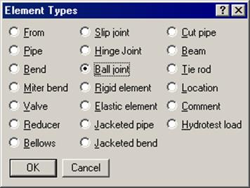
A ball joint is input by typing “Ba” or “Ball” in the Type column or selecting Ball joint from the Element Types dialog.
The Ball joint dialog is shown.
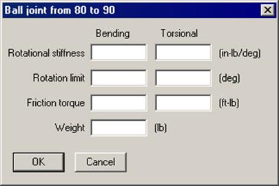
Weight of the ball joint is input in lbf or kgf and NOT its mass. Whenever mass is required for a calculation as in the case of forming Mass matrix for dynamic analysis, or in calculating inertia force as (mass x acceleration) for static seismic analysis, CAEPIPE internally computes the mass to be equal to (weight / g-value).
The rotational stiffnesses, rotation limits and the friction torques are specified independently in the bending and torsional directions. The torsional direction (local x) is determined by the preceding element’s local x. If a preceding element is unavailable, the following element is used to determine the torsional direction. The bending directions (local y and z) are orthogonal to the torsional direction (local x). Bending friction is determined by a resultant of friction torques in local y and z directions. Similarly, bending rotation limit is determined by a resultant of rotational limits in local y and z directions.
The stiffnesses, rotation limits and friction torque values are available from the manufacturer of the ball joints or from their test results. Otherwise, you must use engineering judgment.
The stiffness values may be left blank, in which case CAEPIPE uses a very small value (1 in.-lb./rad) internally to avoid dividing by zero during internal computation.
A rotation limit of zero (0.0) means that the ball joint cannot rotate (i.e., it is rigid) in that direction. A rotation limit of “None” or Blank means that rotation is not limited to a finite value.
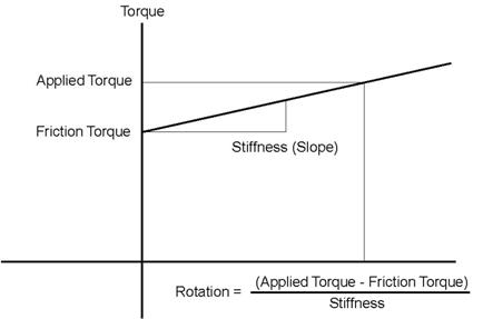
When the applied torque is less than the friction torque, there is no rotation. When the applied torque exceeds the friction torque, rotation is calculated as shown above. When rotation limit is reached, there is no further rotation irrespective of the applied torque.
When the option “Use friction in dynamic analysis” is selected, for modal analysis, CAEPIPE uses three different stiffnesses for a ball joint depending on the magnitude of the applied moment/torque in comparison to the user-specified friction torque. They are as follows:
Case 1: When the applied moment at the ball joint (for the first operating load case when a piping code is selected or for the static case when “Piping code=None” is selected) is less than the friction torque, the friction is not overcome and the ball joint stiffness is internally set to "rigid”, i.e., 1×10¹² (inch-lb./radian).
Case 2: When the applied moment is more than the friction torque, the friction is overcome and the ball joint starts rotating (with the user-specified rotational stiffness being applied). This rotational deformation takes place until the user-specified rotational limit is reached.
So, from the time friction is overcome to the time when the rotational limit is reached, CAEPIPE internally sets an “equivalent stiffness” for the ball joint as given below.
If Kb is the user-specified stiffness for the ball joint,
Rotation = (applied moment – friction torque)/ Kb ……… (1)
The “equivalent stiffness” chosen by CAEPIPE is the slope of the straight line from origin to the point (rotation, applied moment) in the figure given above. In other words,
Kbe = (applied moment/rotation) …….. (2)
Combining (1) and (2), you get
Kbe = (applied moment) x Kb / (applied moment – friction torque) ……. (3)
Case 3: When the actual rotation reaches the user-specified rotational limit for the first operating load case/static case, the rotational stiffness for the ball joint is again set to "rigid”, i.e., 1×10¹² (inch-lb./radian).
For modal analysis, CAEPIPE uses “equivalent stiffness” for ball joints as described under Case 2 above, when the friction torque is exceeded and the computed rotation is yet to reach the specified rotational limit, as long as the option “Use friction in dynamic analysis” is selected. When this option is NOT selected, CAEPIPE ignores the nonlinearities of the ball joint (namely, friction torque and rotational limit) and uses only the user-specified stiffnesses for modal analysis. That is why, despite very small moments, large rotations may be computed (i.e., a check against user-specified rotational limit is not performed).
See the topic Expansion Joints for examples.