Beam
You can model elaborate structural systems inside CAEPIPE alongside the piping to be supported. In simple situations, if the structure is much stiffer than the piping is, you may not need to model the structure at all but simply treat it as rigid (for example: input Rigid for Stiffness in a vertical Limit stop when simulating a support where pipe could rest on a stiff beam). But, in cases where you need to account for structural flexibility, use the Beam element to model structural support systems alongside piping systems.
The material, section and load for a beam are different from those for a pipe. Just as you would define a material/section/load for a pipe, so too should you define a separate material/section/load for a beam. Look for Beam Material, Beam Section, and Beam Load (under Misc menu).
Upon analysis, CAEPIPE reports forces and moments for beam elements.
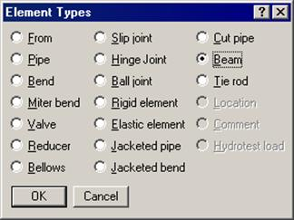
A beam is input by typing “bea” in the Type column or by selecting “Beam” from the Element type dialog.
The Beam dialog is shown.
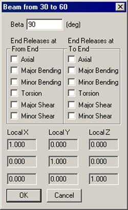
Beta angle is used to define the orientation of a beam’s local axes. See Beam orientation later in this section.
Beam End Releases
Each end of the beam (From and To ends) can be released to simulate the type of structural support you want to model. That is, you can use a combination of releases to specify whether a beam end is fixed, pinned, etc.
Beam material
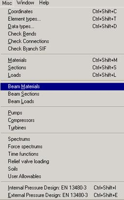
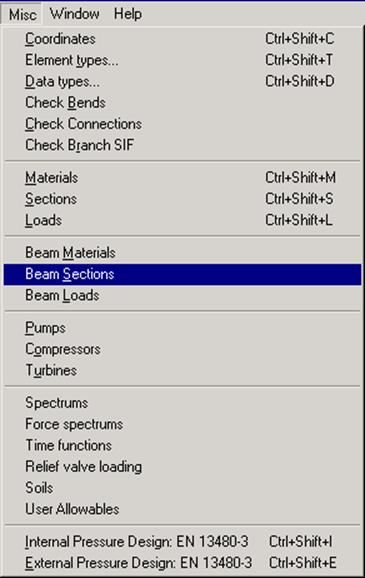
Before you input a beam element, you must define a beam material, section and load. Select Beam materials from the Miscellaneous (Misc) menu in the Layout or List window.
A beam material list window is shown. Double click on an empty row to input a new beam material.
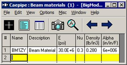
A dialog for inputting beam material is shown.
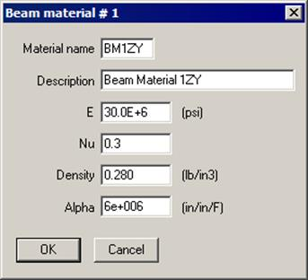
The material name can be up to five alpha-numeric characters to identify the beam material. A more complete description can be entered under Description. Enter modulus of elasticity, Poisson’s ratio (Nu), density of the material and mean coefficient of thermal expansion between Tref and T1/T2/T3/…./T10 in beam load.
Beam section
Select Beam Sections from the “Misc” menu in the Layout or List window.
A list of beam sections is shown. Double click on an empty row to input a new beam section.
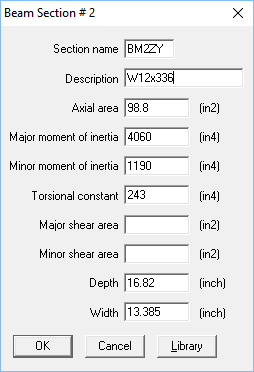
A dialog to input beam sections is shown.
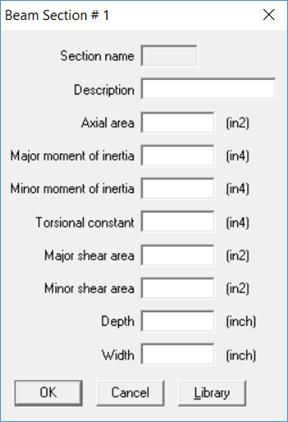
You can either input the data yourself or click on the AISC Library button for a listing of different AISC I-beams, channels, tees, etc., that are built into CAEPIPE or click on the Library button (next to AISC Library) for a listing of different User Defined Beams. Be sure to verify the properties that are shown in the fields after you select a section from the library.
The name can be up to five alpha-numeric characters to identify the beam section. A more complete description can be entered in the Description field.
The axial area, major and minor moments of inertia must be input. Input of torsional constant is optional. If it is not input, it defaults to the sum of major and minor moments of inertia. Input of shear areas is optional. If they are not input, shear deflection is not included. Input of depth and width are optional. Presently, they are used only for rendered plots of the beam.
Dialogs for selecting a beam section from the AISC library are shown below:
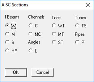
The type of the beam section (e.g., I beam, W (Wide Flange)) is selected from this dialog.
Another dialog which shows various available sections for the particular beam section type is then shown.
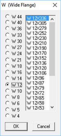
After selecting the section, click on OK and the section properties will be entered in the Beam section dialog.
To create or modify a Beam section library
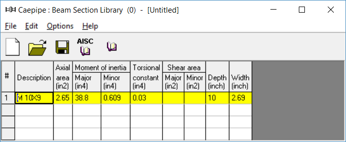
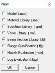
CAEPIPE offers you flexibility in creating your own Beam section libraries (user-defined libraries). That way, you do not feel restricted by the offered choices in Beam sections and can continually keep updating / adding Beam section libraries with your own sections. To create a library: From the Main window, select File > New and click on Beam Section Library.
A List window for Beam section is shown.
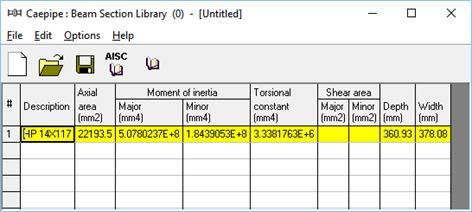
You can, as before, start typing directly into the fields, or enter properties through a dialog. The only difference is that sections in the library do not have names whereas those in a model have names.
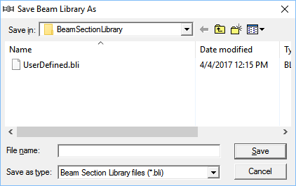
After you are done entering sections, you must save to a Beam Section library file by using the File > Save command.
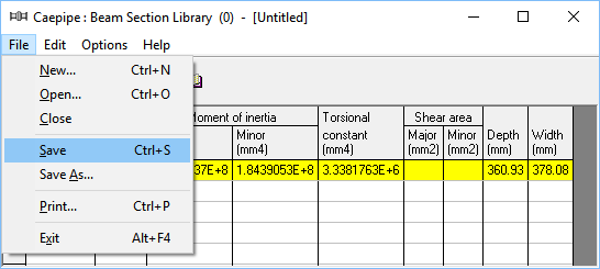
Give the file a suitable name. The file will be saved with a .bli extension.
Beam load
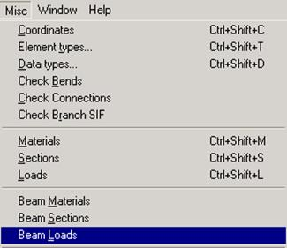
Select Beam Loads from the Misc menu in the Layout or List window.
A list of beam loads is shown.
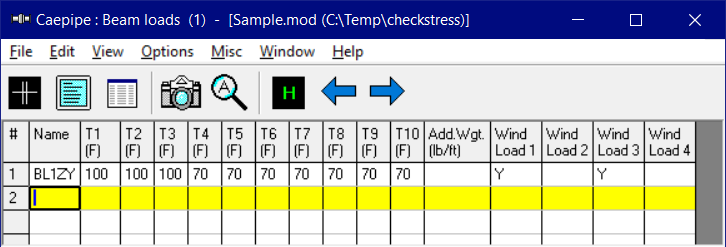
Double click on an empty row to input a new beam load through the beam load dialog or start typing into the fields.
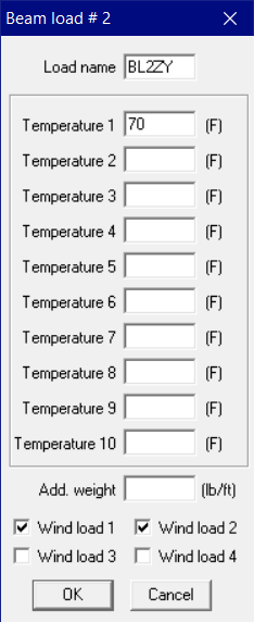
The Load name can be up to five alpha-numeric characters to identify the beam load. You can enter up to 10 temperatures depending on the preset number of thermal loads. The additional weight is a uniform weight per unit length added to the weight of the beam. This could for example be used to add snow load to the beam. Wind load may or may not be applied to the beam element by using the check box for Wind load 1/2/3/4 in the dialog or typing “Y” or “N” for Wind loads in the List window.
Beam orientation
The Beam orientation is determined by the locations of the “From” and “To” nodes and the beta angle of the beam element. The local x-axis of the beam is always from the “From” node to the “To” node. The reference orientation corresponds to beta = 0.0.
A nonzero beta angle (measured from the reference position) rotates the local y- and z-axes of the beam about the local x-axis of the beam in the counter clockwise direction.
The local coordinate system for beams can be displayed for each beam element through the List window (Ctrl+L, select Beams, menu View > Show LCS [for Local Coordinate System]).
Global vertical axis is Y
Beam is not Vertical
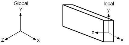
The local y-axis of the beam lies in the local x - global Y plane (i.e., vertical plane) and is in the same positive direction as the global Y axis. The local z-axis is the cross product of the local x and y-axes. Major bending plane is local x-y, that is, Izz = Major moment of inertia and Iyy = Minor moment of inertia.
Beam is Vertical
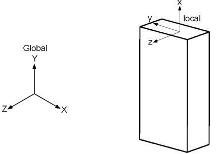
The local z-axis of the beam is in the global Z direction. The local y-axis is in global –X direction. Major bending plane is x-y, i.e., Izz = Major moment of inertia and Iyy = Minor moment of inertia.
Global vertical axis is Z
Beam is not Vertical
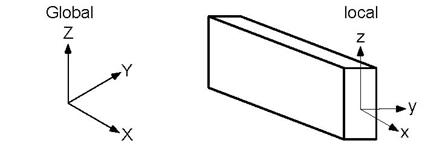
The local z-axis of the beam lies in the local x - global Z plane (i.e., vertical plane) and is in the same positive direction as the global Z-axis. The local y-axis is the cross product of the local z and x-axes. Major bending plane is x-z, that is, Iyy = Major moment of inertia and Izz = Minor moment of inertia.
Beam is Vertical
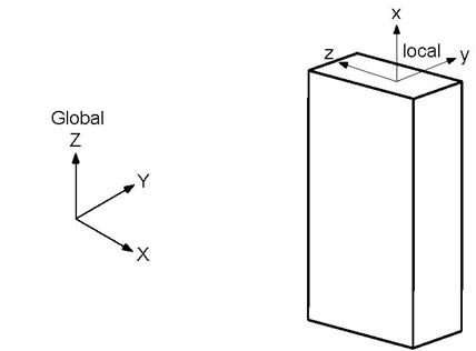
The local y-axis of the beam is in the global Y direction. The local z-axis is in global –X direction. Major bending plane is x-z, i.e., Iyy = Major moment of inertia and Izz = Minor moment of inertia.
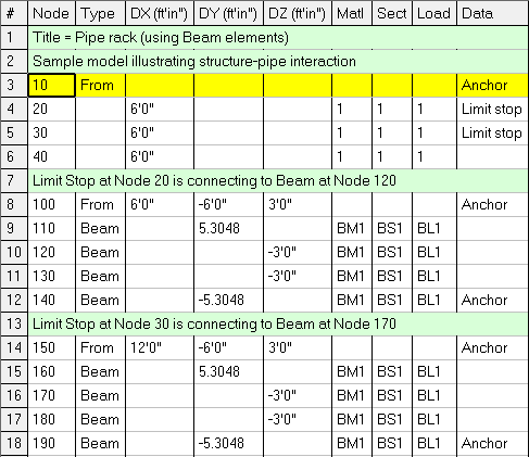
Example 1: Pipe Rack using Beams
Here, you see how to use a beam element to construct a pipe rack and connect the beam to the pipe so that CAEPIPE can account for the rack’s flexibility. The procedure is simple. First, you need to create a beam material, section and load in addition to pipe material, section and load.
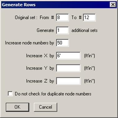
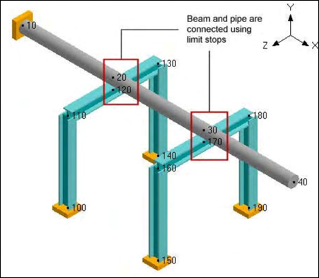
As the Layout window shows, model the piping (nodes 10 to 40) and the first beam support (nodes 100 to 140). Then, create the second beam support (nodes 150 to 190) using the Generate command (under Edit menu in the Layout window). Finally, connect piping at nodes 20 and 30 to beam nodes 120 and 170 using limit stops.
The “Generate” dialog is shown below:
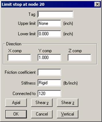
The “Limit Stop” dialog is shown below:
The graphics is shown below:
Example 2: Base Supported Bend using a Beam
See Example 7 in the Bend section of this manual for modeling a base supported bend using a beam.