Branch SIF
A tee is modeled using three pipes that come together at a node, which should be designated as a “Tee” using the Branch SIF data type. If not, then CAEPIPE cannot calculate a code-specified SIF for the tee to use in stress calculations.
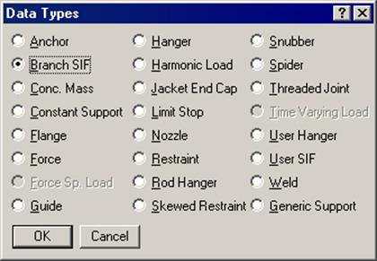
A Stress Intensification Factor (SIF) type for a tee can be input by typing “br” in the Data column or selecting “Branch SIF“ from the Data types dialog.
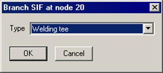
The Branch SIF dialog is shown.
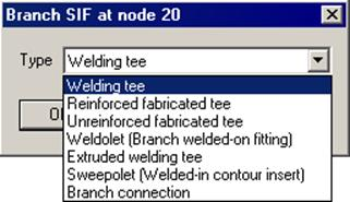
The type of the branch SIF can be selected from the Type drop-down combo box. Depending on the piping code selected, different types of branch SIFs may be available. Typical branch SIF types (for B31.1 piping code) are shown below.
A few branch SIFs may need additional input; for example, in the case of a reinforced fabricated tee, a pad thickness is required.
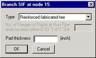
The field “No. of Flanges or Rigids at Run Pipe ends…” shown above is available only when the Option “Use B31J for SIFs and Flexibility Factors” is turned ON through Layout window > Options > Analysis for B31.x codes. This field can be blank or entered as 1 or 2.
When entered as either 1 or 2, CAEPIPE will multiply the flexibility factors for the Branch by a factor ‘c’ provided in “Table 1-3 – Flanged End Corrections” of ASME B31J-2017. For more details, see the section titled “ASME B31J-2017” from Code Compliance Manual.
CAEPIPE differentiates between a header (run) and a branch line based on their ODs. So, when CAEPIPE finds two lines with ODs of 8 inches and 6 inches coming together at a node, it designates the 8 inch line as the header (or main) line with the 6 inch line designated as the branch line (this is also how you would model a reducing tee).
When the header and the branch lines have the same ODs, reduce the branch OD slightly so that the header and the branch lines are properly designated (e.g., ODheader = 168.4 mm, ODbranch = 168.3 mm).
Note:
Starting CAEPIPE Version 13.20, the algorithm for identifying the Run and Branch elements has been updated. The new approach now uses the direction vectors of the connecting pipes at a branch connection, rather than relying on the Outer Diameters of the Run and Branch. Hence, it is not necessary for the user to reduce the branch OD when the header and branch lines have the same ODs.
Say you want to model a reducing tee as shown in the provided “Sample.mod”. It’s an 8”x6” reducing tee. First, we need to model the three pipes – two for the run (nodes 20 to 30 and 30 to 40), one for the branch (nodes 30 to 60), which will be assigned the 6” section. Each pipe section can have its own OD/Thickness. Lastly, designate the common node as a (Butt) Welding Tee.
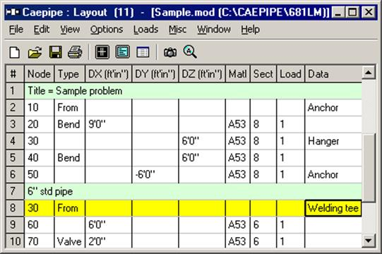
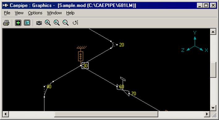
The Tee is as shown at node 30 in the graphics window below.
A “latrolet” or a lateral tee (commonly, the branch is at a 45° angle from the header) or a Y-joint is modeled like a regular tee (as above). But, the SIF for this joint needs to be input by you after consultation with the tee/joint manufacturer. Use a “User-SIF” data type at the common node to specify the SIF. See topic on Tees for more information.