Bend
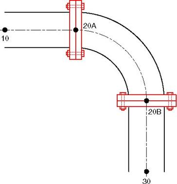
In CAEPIPE, the term Bend refers to all elbows and bends (custom-bent pipes). An elbow comes prefabricated with a standard bend radius (short or long radius) whereas a bend is custom- made from bending a straight pipe with a specified bend radius. Geometrically, a bend is a curved pipe segment which turns at an angle (typically 90° or 45°) from the direction of the run of the pipe. Some of the items associated with a bend are shown below.
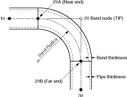
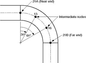
Node 20 is the Bend node, also referred to as the Tangent Intersection Point (TIP). As you can see from the figure, it is not physically located on the bend. Its only purpose is to define the bend. CAEPIPE automatically generates the end nodes of the curved portion of the bend (nodes 20A and 20B), called the near and far ends of the bend. The bend end nodes (20A and 20B in the figure) may be used to specify data items such as flanges, hangers, forces, etc.
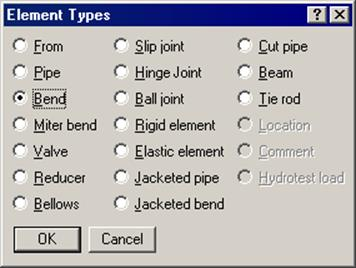
A bend is input by typing “b” in the Type column or selecting “Bend” from the Element Types dialog.
If you need to modify an existing bend, double click on it or press Ctrl+T (Edit type) to bring up the Bend dialog.
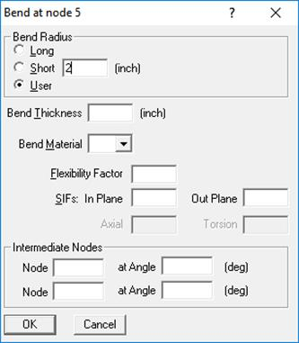
Bend Radius
The radius of a bend (measured along the centerline of the bend) can be specified as Long, Short, or User (defined) by one of the radio buttons for Bend Radius. CAEPIPE has long and short radii built-in for standard ANSI, JIS, DIN and ISO pipe sizes. For nonstandard pipe sizes, Long radius is equal to 1.5 times the pipe OD and Short radius equal to the pipe OD.
Bend Thickness
Input the wall thickness of the bend if different from the preceding pipe’s thickness. If specified, the Bend Thickness applies only to the curved portion of the bend (node 20A to node 20B in the figure above).
Bend Material
If the material of the bend is different from that of the preceding pipe, select the Bend Material from the drop down combo box. The Bend Material, if specified, applies only to the curved portion of the bend (node 20A to node 20B in the figure above).
Flexibility Factor
This factor is automatically calculated for standard elbows according to the piping code chosen. If you have your own Flexibility Factor, enter it here instead of the piping code specified Flexibility Factor. A value of 2.0, for e.g., will mean that the bend is twice as flexible as a pipe of the same length.
SIFs
These factors are automatically calculated for standard elbows according to the piping code chosen. If you have your own, specify them here (useful for FRP bends, for example), which will be used instead of the piping code specified SIFs. If User SIFs are also specified at bend nodes (A and/or B nodes), they will be used instead of the bend SIFs or code specified SIFs.
Intermediate Nodes
An intermediate node, located in between the ends of the bend, may be required in some situations to specify data items such as flanges, hangers, forces, etc. You can create an intermediate node by giving a (new) node number and an angle for it, which is measured from the near end of the bend (node 20A in figure). Up to two such nodes may be input. Note that the intermediate nodes 13 and 16 shown below are at angles of 30° and 60° respectively from node 20A (near end). The intermediate nodes can be used for specifying data items such as flanges, hangers, forces, etc.
Note:
CAEPIPE will issue a message "Angle is too short" when the User tries to add an intermediate node at an Angle less than 4.5 degree. Similarly, will issue a message "Angle is too large" when the user tries to add an intermediate node at an Angle less than 4.5 from the Far end.
Bend Examples
Some examples follow. They illustrate some common modeling requirements.
Example 1: 90° Bend
Example 2: 45° Bend and Pipe routing along a smooth curve
Example 3: 180° Bend
Example 4: Flanged Bend
Example 5: Reducing Bend
Example 6: Bend Supported by a Hanger
Example 7: Base Supported Bend
Example 8: Circular Piping
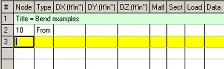
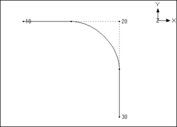
To simplify the discussion of bend modeling, it is assumed that the material, section (8” STD), load and the first node (10) are already defined. It is also assumed that the bend has long radius (12”) and the cursor is placed in row #3.
Example 1: 90° Bend
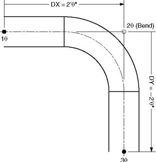
u Press Tab in row #3. Node 20 will be automatically assigned and the cursor will move to the Type column, type “B” (for Bend), Tab to DX, type 2. Enter material, section, load and press Enter. The cursor moves to the next row (#4).
u Tab to the DY column. The next Node 30 is automatically assigned. In DY column, type -2 and press Enter. This completes the bend input.
Example 2: 45° Bend and Pipe routing along a smooth curve
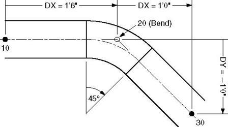
u Press Tab in row #3. Node 20 will be automatically assigned and the cursor will move to the Type column. type “B” (for Bend), Tab to DX, type 1’6”. Enter material, section, load and press Enter. The cursor moves to the next row (#4).
u Tab to the DX column. The next Node 30 is automatically assigned. In the DX column, type 1, Tab to DY and type -1, then press Enter. This completes the bend input.
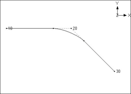
To route a pipe along a smooth curve, you need to split that curve into a number of circular arc segments. Each circular arc segment is then defined as a bend element by giving the offsets (DX, DY and DZ) from the previous Point or Bend Tangent Intersection Point (TIP) to the next TIP, as done for the 450 bend above. You continue this process until the routing along the smooth curve is completed.
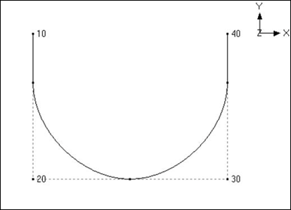
Example 3: 180° Bend
A 180° bend or U-bend, is often used in an expansion loop to relieve thermal stresses in the piping system. It is modeled as two 90° bends back-to-back.
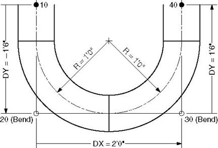
u Press Tab in row #3. Node 20 will be automatically assigned and the cursor will move to the Type column. type “B” (for Bend), Tab to DY, type –1’6”. Enter material, section, load and press Enter. The cursor moves to the next row (#4).
u Press Tab. Node 30 will be automatically assigned and the cursor will move to the Type column. type “B” (for Bend), Tab to DX, type 2. (DX is 2’ because 8” std long radius bend has 12” radius and since these two bends are back to back, DX = 2R). Press Enter and the cursor moves to the next row (#5).
u Tab to the DY column. The next Node 40 is automatically assigned. In DY column, type 1’6”, then press Enter. This completes the bend input.
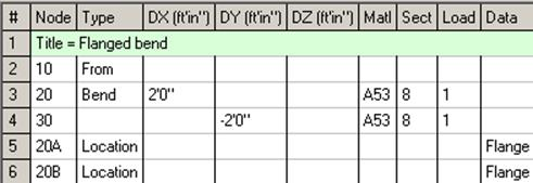
Example 4: Flanged Bend
Bends are often connected to the adjacent pipe sections with flanges. A flange may exist on one or both sides of the bend. Flange weight may have a significant effect on the pipe stresses. Also, the stress intensification and flexibility factors for a bend will decrease if one or both of the ends are flanged.
Model the bend as in Example 1. Then input flanges at nodes 20A and 20B. Since these are internally generated nodes, i.e., they do not normally appear in the Layout window, it is necessary to specify input at these nodes using the Location type. To input the flange at node 20A, in row #5, type 20A for Node, Tab to Type column and type “L” for Location. This opens the Data Types dialog.
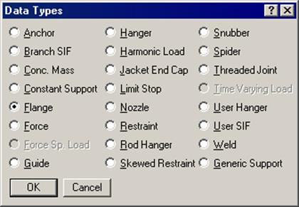
Select Flange as the data type and click on OK. This opens the Flange dialog.
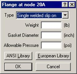
Select the Type of the flange from the drop-down combo box, e.g., Single welded slip-on flange. To get the weight of the flange, click on the Library button.
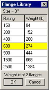
Select the pressure rating for the flange (e.g., 600) and press Enter. The weight of the flange is automatically entered in the Flange dialog. Press Enter again to input the flange.
Repeat the same procedure for the flange at node 20B.
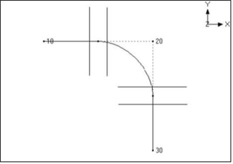
The graphics is shown below:
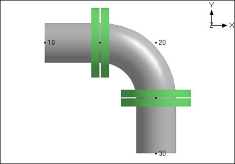
The rendered graphics is shown below:
Example 5: Reducing Bend
CAEPIPE does not have a reducing bend element. A reducing bend may be modeled using an average OD (outside diameter) and average thickness of the large and small ends of the bend. The bend radius of the reducing bend should be input as user bend radius. The Stress Intensification Factor (SIF) of the reducing bend, if available, should be input as Bend SIF.
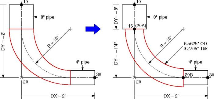
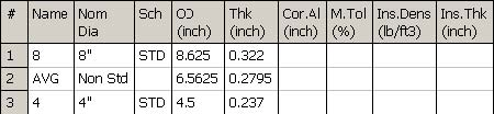
u The 8” std pipe (OD = 8.625”, Thk = 0.322”) with Name = 8 is already defined. Now define a 4” std pipe (OD = 4.5”, Thk = 0.237”) with Name = 4.
The average OD of the two sections is (8.625 + 4.5) / 2 = 6.5625” and the average Thickness is (0.322 + 0.237) / 2 = 0.2795”.
Define a “Non Std” section with Name = AVG, OD = 6.5625” and Thickness = 0.2795”.
The list of sections is shown below.
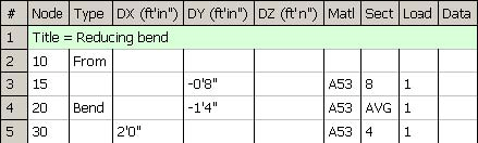
u Note that the section specified on the Bend row in the Layout window applies to the curved portion of the Bend (between the A and B nodes) as well as to the straight portion from the preceding node to the A node. In this case, we want to assign the section “AVG” only to the curved portion and assign the section “8” to the straight portion. This can be done by defining an additional node that is coincident with the A node thus making the straight portion of the bend zero length.
u In row #2, the first node (10) is already defined and the cursor is placed in row #3. Type 15 for Node, Tab to DY, type -8”. Enter material (1), section (8), load (1) and press Enter. The cursor moves to the next row (#4).
u Press Tab. Node 20 is automatically assigned and the cursor will move to the Type column, type “B” (for Bend), Double click in the Type column to edit the Bend. Click on the User Bend Radius button and type 16 for bend radius. Press Enter to modify the Bend and return to the Layout window. Tab to DY, type -1’4”. Tab to the section column and type “AVG”. Then press Enter. The material and load are copied from the previous row and the cursor moves to the next row(#5).
u Tab to the DX column. The next Node 30 is automatically assigned. In DX column, type 2’. Tab to section column, type 4 and then press Enter. This completes the reducing bend input.
The Layout window is shown below:
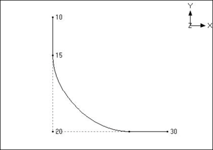
The graphics is shown below:
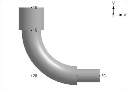
The rendered graphics is shown below:
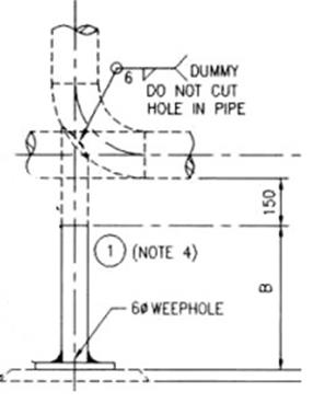
Example 6: Bend Supported by a Hanger or Resting Support
Bend supported in the middle by a hanger or resting support as shown in the figures below can be modeled by defining an intermediate node at Bend.
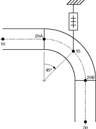
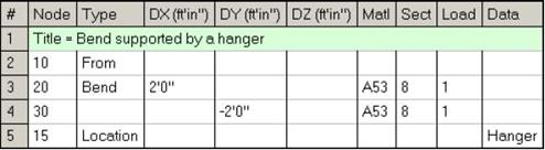
Assuming that the Bend is supported in the middle of the hanger, Model the bend as in Example 1. The hanger is input at node 15, which is in the middle of the bend. Node 15 is created as an intermediate node on the bend as follows:
Double click on the bend (in the type column of the Layout window) to edit it. The bend dialog is shown.
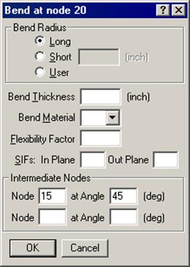
Under intermediate nodes, type 15 for node and 45 for its angle, then click on OK. This creates an intermediate node 15 at 45° from the node 20A (near end of the bend) as shown in the figure above.
Since node 15 does not show in the Layout window, it is necessary to specify data input at this node using the Location type. To input the hanger at this node, in row #5, type 15 for Node, Tab to Type column and type “L” for Location. This opens the Data Types dialog.
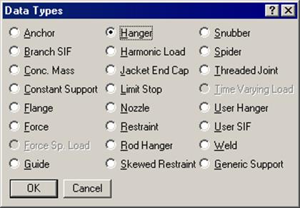
Click on Hanger, the hanger dialog is shown.
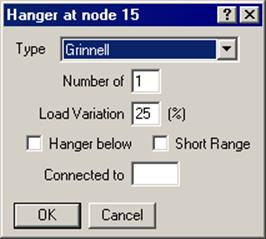
Click on OK to accept the default hanger and a hanger is entered at node 15.
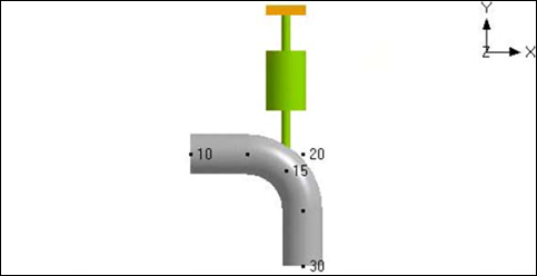
The rendered graphics is shown next.
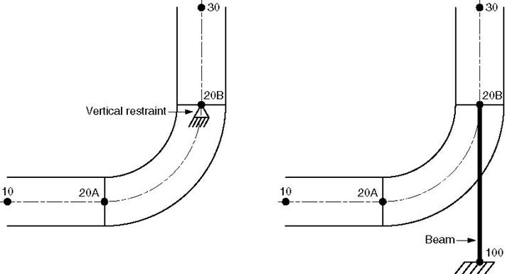
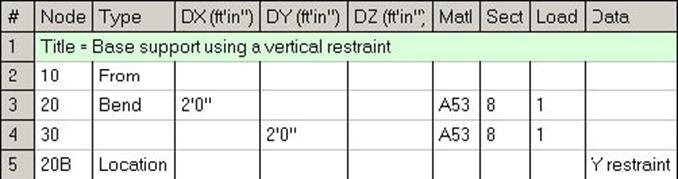
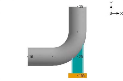
Two examples of base supported bends are shown below. In the figure on the left, the support is modeled using a rigid vertical restraint. In the figure on the right the support is modeled using a beam element.
Vertical Restraint Support
u Model the bend at node 20 as before.
u To put a vertical restraint at node 20B, type 20B for node and “L” for Location. This will open the Data types dialog.
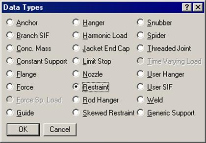
Double click on Restraint. This will open the Restraint dialog.
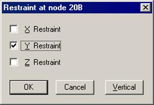
u Click on the Vertical button to check the Y or Z restraint (depending on the vertical axis) and click on OK.
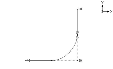
The Layout window is shown below:
The graphics is shown below:
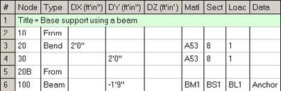
Beam Support
u Model the bend at node 20 as before.
u Create a beam material, section and load as described earlier under the Beam section in the Technical Reference manual.
u Input a beam element from node 20B to node 100.
Type 20B in the Node column and “f” (for From) in the Type column to create a starting point. Press Enter to move to the next row.
Type 100 in the Node column and “bea” (for Beam) in the Type column. In the DY column, type the beam length with a negative sign (since the beam is going downward from node 20B to node 100). Type the beam material, beam section and beam load names in the Matl, Sect and Load columns. In the Data column type “a” to input an Anchor.
The Layout window is shown below:
The rendered graphics is shown below:
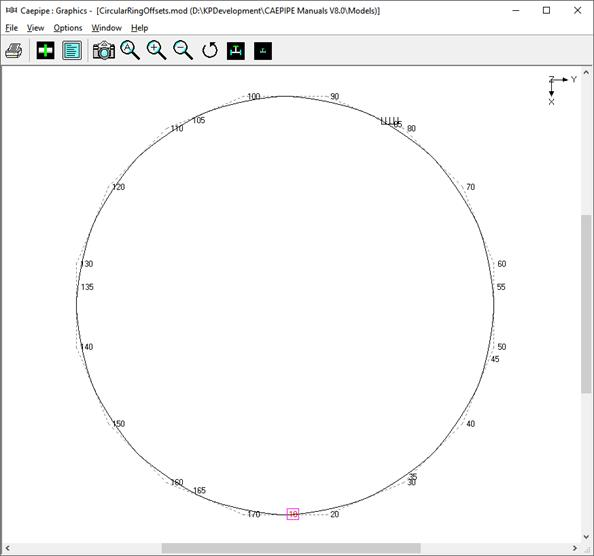
Example 8: Circular Piping
Circular piping around the Nuclear Containment or Tank can be modeled using a series of Bends. Depending upon the number of nodes required to represent the layout and its supports, one can decide the required bend angle.
In this example, Bends with 22.5degrees are chosen to represent the layout. The center line diameter of the Circular pipe layout is 96” and the Section property is 3” Schedule 40.
Origin of the Circular piping is at absolute coordinates Xo=150”, Yo=30” and Zo=0.0”.
Vertical Axis is chosen as “Z”.
With reference to the Origin, absolute coordinate for Node 10 is
X' =150”+Radius (96”) = 246”; Y'=30” and Z' =0.0”.
Bend Angle chosen (A) = 22.5 deg.
Distance between Origin and Tangent Intersection Point (TIP) = R' = Radius / COS(A/2) = 96/COS(11.25) = 97.88”.
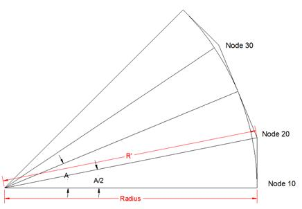
Using the above information, absolute coordinates and the offset distances for TIP nodes are computed and presented in the Table below.
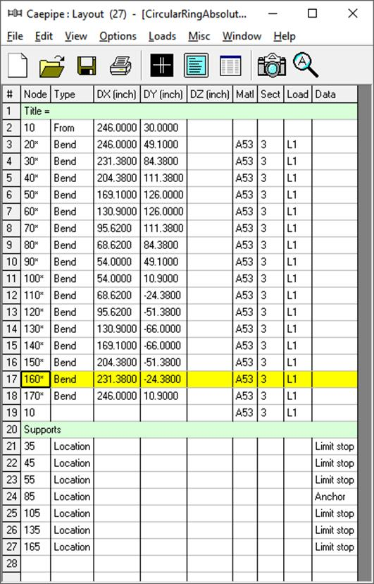
Two layouts are generated.
The first layout is generated using absolute coordinates and hence under the Node column you will see a “*” after the Node number in CAEPIPE layout, meaning that DX, DY and DZ values are not offsets, instead they are absolute coordinates for the Node being input..
The second layout is generated using the Offset Distances listed in the table below.
|
Ring Radius = Bend Radius (in)
|
96
|
Bend Angle
|
22.5
| |||
|
|
Xo (in)
|
Yo (in)
|
Zo (in)
| |||
|
Absolute Coordinates of Circular Ring Center
|
150
|
30
|
0
| |||
|
|
X' (in)
|
Y' (in)
|
Z' (in)
| |||
|
Absolute Coordinates for Node 10
|
246
|
30
|
0
| |||
|
| ||||||
|
TIP Node
|
Angle (B) @ Tangent Intersection Point (TIP) (Deg)
|
R' = Distance between Origin and TIP
(in)
|
Absolute Coordinates
|
Offset Distances
| ||
|
X' = Xo + [COS(B) x R']
(in)
|
Y' = Yo + [SIN(B) x R']
(in)
|
DX
(in)
|
DY
(in)
| |||
|
20
|
11.25
|
97.88
|
246.00
|
49.10
|
0.00
|
19.10
|
|
30
|
33.75
|
97.88
|
231.38
|
84.38
|
-14.62
|
35.28
|
|
40
|
56.25
|
97.88
|
204.38
|
111.38
|
-27.01
|
27.01
|
|
50
|
78.75
|
97.88
|
169.10
|
126.00
|
-35.28
|
14.62
|
|
60
|
101.25
|
97.88
|
130.90
|
126.00
|
-38.19
|
0.00
|
|
70
|
123.75
|
97.88
|
95.62
|
111.38
|
-35.28
|
-14.62
|
|
80
|
146.25
|
97.88
|
68.62
|
84.38
|
-27.01
|
-27.01
|
|
90
|
168.75
|
97.88
|
54.00
|
49.10
|
-14.62
|
-35.28
|
|
100
|
191.25
|
97.88
|
54.00
|
10.90
|
0.00
|
-38.19
|
|
110
|
213.75
|
97.88
|
68.62
|
-24.38
|
14.62
|
-35.28
|
|
120
|
236.25
|
97.88
|
95.62
|
-51.38
|
27.01
|
-27.01
|
|
130
|
258.75
|
97.88
|
130.90
|
-66.00
|
35.28
|
-14.62
|
|
140
|
281.25
|
97.88
|
169.10
|
-66.00
|
38.19
|
0.00
|
|
150
|
303.75
|
97.88
|
204.38
|
-51.38
|
35.28
|
14.62
|
|
160
|
326.25
|
97.88
|
231.38
|
-24.38
|
27.01
|
27.01
|
|
170
|
348.75
|
97.88
|
246.00
|
10.90
|
14.62
|
35.28
|
Layout using Absolute Coordinates
Layout using Offset Distances
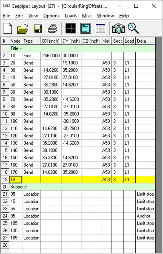
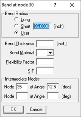
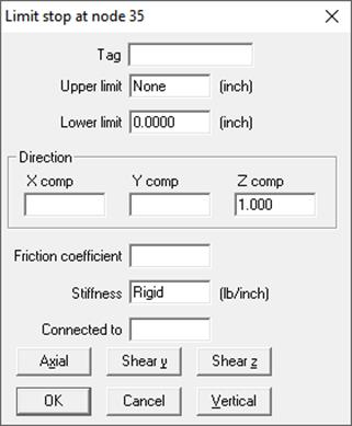
As an example, shown below are the snap shots to split the Bend at Node 30 with an intermediate Node 35 and to place a Limit Stop at that intermediate Node 35.
Example 9: Bend with Large Bending Angle
In CAEPIPE, you can model a bend with included angle up to 179.9 degree.
In order to model the Bend, you need to input (a) the Distance between the Starting Point of the Pipe and the Tangent Intersection Point (TIP) of the Bend, and (b) the Distance between TIP of the Bend and the End Point of the Pipe. Of course, you need to manually determine the X, Y and Z coordinates for the TIP to determine the above mentioned distances.
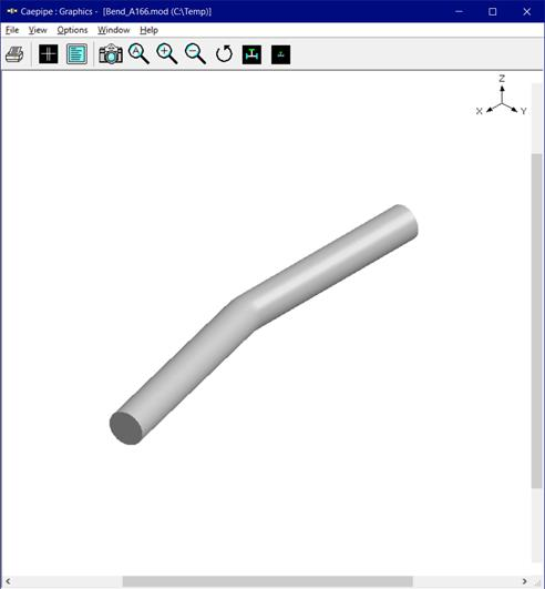
Sample CAEPIPE model shown below has a Bend with included angle of 166 degree at Node 20. In the Sample model given below, the Distance between the Start Point of the Pipe and TIP of Bend is assumed to be 1000 mm. Similarly, the Distance between the TIP and the End point of the Pipe is assumed to be 1000 mm. In order to generate a Bend for the above dimension, input the following in CAEPIPE Layout Window.
1. Node 10, From, X = 0, Y = 0 and Z = 0.
2. Node 20, Bend, X = 1000, Y = 0 and Z = 0 with Bend Radius = 35 mm.
3. Node 30, Pipe, X = 970 mm (= Cos(14)*1000mm), Y = 241.9 mm (= Sin(14)*1000).