Compressor
Pumps, compressors, turbines, air cooled heat exchanger and fired heaters in CAEPIPE, referred to as equipment, are each governed by an industry publication - API (American Petroleum Institute) publishes an API 610 for pumps, ANSI (American National Standards Institute) publishes an ANSI/HI 9.6.2 for Rotodynamic Pumps, API 617 for compressors and NEMA (National Electrical Manufacturers Association) publishes the NEMA SM-23 for turbines, API 661 for air cooled heat exchangers and API 560 for fired heaters. These publications provide guidelines for evaluating nozzles connected to equipment among other technical information including the items relevant to piping stress analysis – criteria for piping design and a table of allowable loads.
Modeling the equipment is straightforward since it is assumed rigid (relative to connected piping) and modeled only through its end points (connection nozzles).
1. In your model, anchor all the nozzles (on the equipment) that need to be included in the analysis.
2. Specify these anchored nodes during the respective equipment definition through Misc. menu > Pumps/Compressors/Turbines/Air Cooled Heat Exchangers/Fired Heaters in the Layout window.
CAEPIPE does not require you to model all the nozzles nor their connected piping. For example, you may model simply one inlet nozzle of a pump with its piping. Or, you may model one pump with both nozzles (with no connected piping) and impose external forces on them (if you have that data). Further, there is no need to connect the two anchors of the equipment with a rigid massless element like required in some archaic methods.
A compressor (like a turbine or a pump) is input by selecting “Compressors” from the Misc menu in the Layout or List window. Upon analysis, an API 617 compressor compliance report is produced. See the section titled “Equipment Qualification” from Code Compliance Manual for related information.
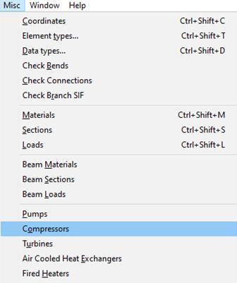
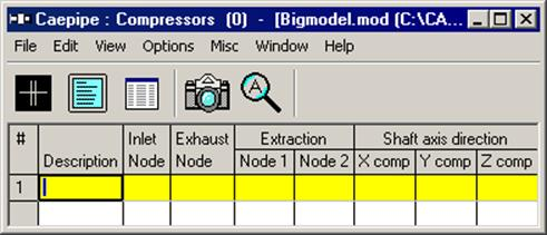
Once you see the Compressor List window, double click on an empty row for the Compressor dialog and enter the required information.
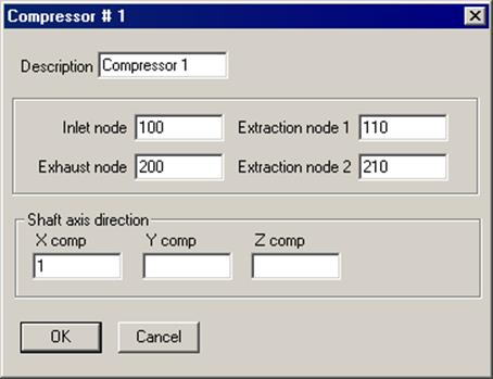
A short description to identify the compressor may be entered for Description. The nozzle nodes must be anchors and the shaft axis must be in the horizontal plane. Some of the nozzle nodes may be left blank if they are not considered as a part of the piping system being analyzed (e.g., extraction nodes).
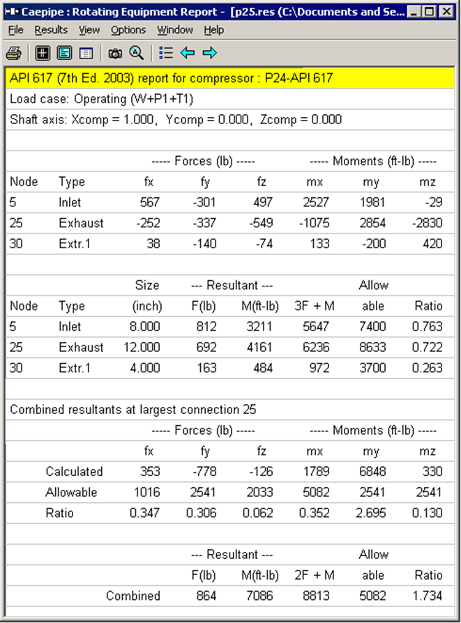
If you have input multiple temperatures, corresponding reports for additional operating load cases are shown.