Flange and Bolt Stresses
Flange joints are essential components in all pressurized systems; they are also one of the most complex. Many factors are involved in determining the successful design and operation of a bolted flange joint service, namely, the interaction between the bolting, flange, and gasket as well as important non-linear variables such as friction and gasket properties. The Pressure Vessel and Piping Codes were developed with safety in mind; they provide a method for sizing the flange and bolts to be structurally adequate for the specified design conditions.
The Flange Qualification module implemented in CAEPIPE addresses the design rules contained in the ASME Section VIII, Division 1, Appendix 2 on bolted flange connections with gaskets.
These design rules will help you to obtain better insight into a flange joint's tendency to leak, beyond that provided by the rudimentary (yet indicative) flange report produced by a piping analysis, as seen in the previous section. You can examine the flange and bolt stresses arising from the bolt tightening loads required for a leakage-free joint.
The Flange Qualification module assumes that you already have flanges and gaskets picked out for your system and performed a piping flexibility analysis of that system with CAEPIPE, which will have produced a flange report as given above in the previous section depending upon the piping code selected.
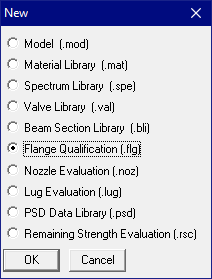
Note that this Flange Qualification module to calculate flange and bolt stresses is separate from a piping stress model file and can be accessed from File Menu > Open/New command.
The Flange Qualification module performs three (3) qualifications namely,
1. Flange Allowable Moment as per NC3658.3 of ASME Section III Class 2,
2. Flange Stresses for Operating Case as per Appendix 2 of ASME Section VIII Division 1, and
3. Flange Stresses for Gasket Seating Case as per Appendix 2 of ASME Section VIII Division 1.
Out of the three (3) qualifications listed above, Bending / Torsional Moment entered in “Flange Qualification” module is used ONLY in calculating the Allowable Flange Moment as per NC3658.3 of ASME Section III Class 2. The same results are also shown in “Flange report” under CAEPIPE Results. The equation involved in Flange Joint analysis is given below.
Note: Flange Joint analysis as per NC 3658.3 is valid for ASME B16.5 flanges with Bolt Stress at 100 deg. F is greater than or equal to 20000 psi (138 MPa). So, please ensure that the Bolt Stresses at 100 deg.F is greater than or equal to 20000 psi.
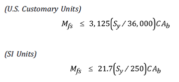
Ab = total cross-sectional area of bolts at root of thread of section of least diameter under stress, in2 or mm2
C = bolt circle diameter, in or mm.
Sy = Yield stress of flange material at Peak Temperature = 1.5 * Flange Allowable Stress at Peak Temperature (assumed inside CAEPIPE, as Allowable Stress is generally 2/3 of Yield Stress at temperatures well below creep)
Mfs = bending or torsional moment applied to the joint due to weight, thermal expansion of the piping, sustained anchor movement, relief valve steady-state thrust and other sustained mechanical loads applied to the flanged joint during the design or service condition, in-lb or N.mm.
On the other hand, Flange Stresses and Flange Rigidity Factors computed as per ASME Section VIII Division 1 Appendix 2 are independent of Axial Force and Bending Moment as observed from the detailed write-up given in the Section titled “Flange Qualification” of CAEPIPE Code Compliance Manual.
Because this module accepts bending / torsional moment at a flange as input among many others, you will need to first create in CAEPIPE your pipe stress model that includes flanges (which you need to validate) and generate a Flange Report as shown above. Such a report will contain the information you can now use in the Flange Qualification module to calculate flange and bolt stresses.
When you first create a new Flange Qualification file, it comes populated with default values for a sample flange (see example 1 later on in this topic).
Double-clicking anywhere in the previous screen (or Edit menu > Edit (Ctrl+E)) opens a dialog with input fields (with default values) you can edit. You will need to enter all of your flange data in this dialog. The different parameters you see here are explained in detail in the Section titled “Flange Qualification” of the Code Compliance manual.
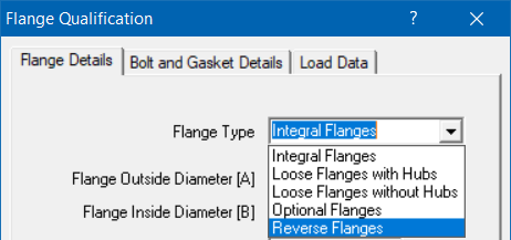

Required flange input information is organized into three Property tabs – Flange Details, Bolt and Gasket Details, and Load Data, the last of which accepts data from a piping model’s Flange Report. Once all the data is input, save the model (Flange Qualification filenames will have a .flg extension). Now, select File menu > Analyze to calculate flange stresses, which will be shown right below the input information.
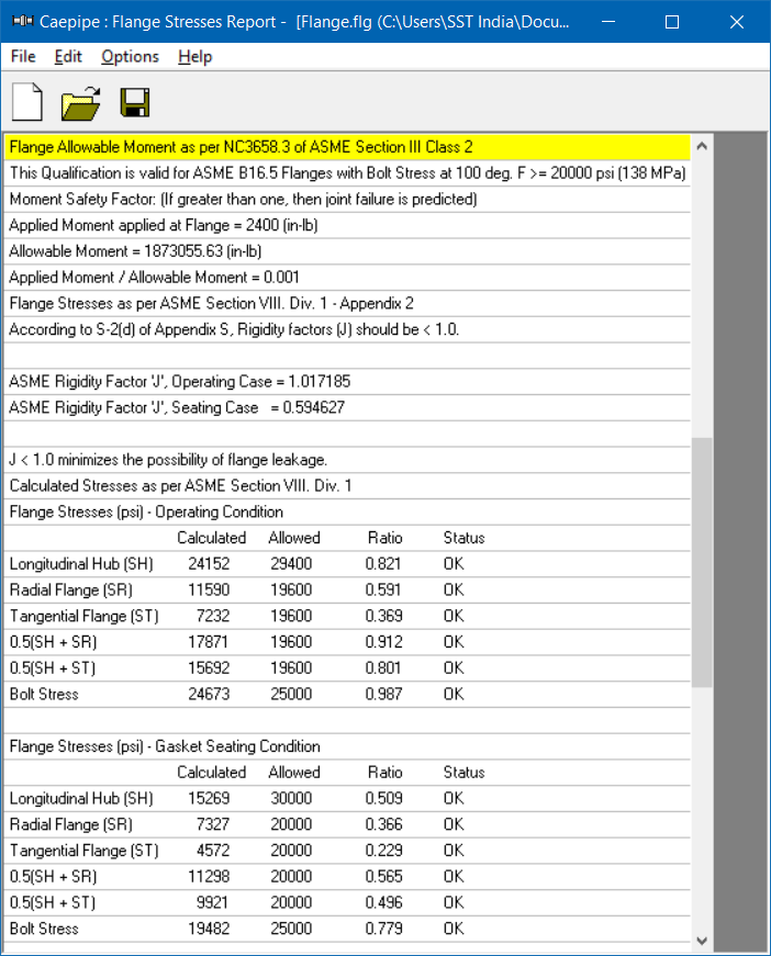
There are three main sections in the shown results:
· Flange Equivalent Pressure (same as the one shown in piping model results > Flange Report),
· Flange stresses in the Operating condition, and
· Flange stresses in the Gasket seating condition
Flange Qualification Module Menus
Use these numbers in accordance with the ASME Section VIII publication and your engineering judgment to qualify these flanges for use in your piping systems.
File Menu
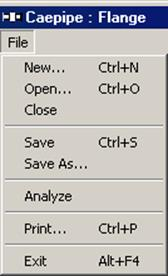
Analyze
Analyze command calculates the flange and bolt stresses and compares them to the input allowable stresses.
Print
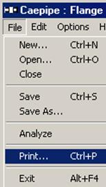
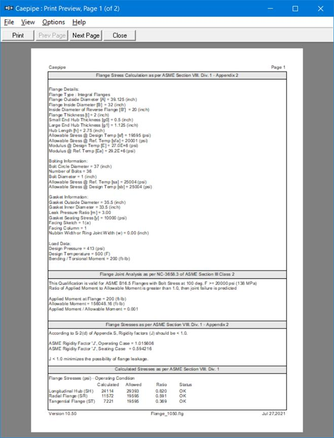
You can print a Flange Report by using the Print command. You can also preview the report by clicking the Preview button on the print dialog.
Edit Menu
Edit
You can edit the Flange, Bolt, and Gasket Details, as well as Load Data by clicking the Edit command.
Flange Qualification Window
You can edit the Flange, Bolt, and Gasket Details, as well as Load Data by clicking the Edit command.
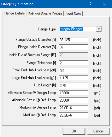
Flange Details Tab
Modify the flange details using this window.
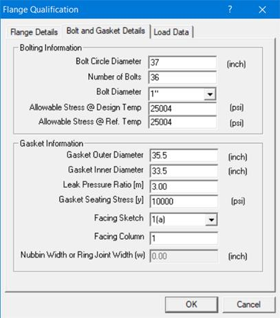
Bolt and Gasket Details Tab
Modify the bolt and gasket details using this window.
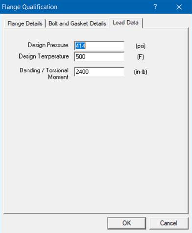
Load Data Tab
Modify the load data using this window.
Options Menu
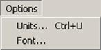
Units
See Units in the Layout Window Options Menu section of the CAEPIPE User’s Manual.
Font
See Font in the Layout Window Options Menu section of the CAEPIPE User’s Manual
Sample Problem
Problem 1:
(Example on page 19 in Chapter 40 “Bolted-Flange Joints and Connections” by William J. Koves on “Companion Guide to the ASME Boiler & Pressure Vessel Code” by K .R. Rao [2001], American Society of Mechanical Engineers, U.S.)
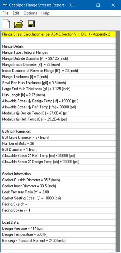
Flange Details:
Flange Type : Integral Flanges
Flange Outside Diameter [A] = 39.125 (inch)
Flange Inside Diameter [B] = 32 (inch)
Flange Thickness [t] = 2 (inch)
Small End Hub Thickness [g0] = 0.5 (inch)
Large End Hub Thickness [g1] = 1.125 (inch)
Hub Length [h] = 2.75 (inch)
All. Stress @ Design Temp [sf] = 19600 (psi)
All. Stress @ Ref. Temp [sfa] = 20000 (psi)
Modulus @ Design Temp [E] = 2.7E+7 (psi)
Modulus @ Ref. Temp [Ea] = 2.92E+7 (psi)
Bolting Information:
Bolt Circle Diameter = 37 (inch)
Number of Bolts = 36
Bolt Diameter = 1 (inch)
All. Stress @ Ref. Temp [sa] = 25000 (psi)
All. Stress @ Design Temp [sb] = 25000 (psi)
Gasket Information:
Gasket Outside Diameter = 35.5 (inch)
Gasket Inner Diameter = 33.5 (inch)
Leak Pressure Ratio [m] = 3.00
Gasket Seating Stress [y] = 10000 (psi)
Facing Sketch = 1
Facing Column = 1
Load Data:
Peak Pressure = 414 (psi)
Peak Temperature = 500 (F)
Bending Moment = 200 (ft-lb)
Comparison of Results
|
Flange Stresses
|
Text Book Results
(psi)
|
CAEPIPE
(psi)
|
CAESAR II
(psi)
|
|
Operating condition
|
|
|
|
|
Longitudinal Hub (SH)
|
24150
|
24152
|
24227
|
|
Radial Flange (SR)
|
11590
|
11590
|
11636
|
|
Tangential Flange (ST)
|
7230
|
7232
|
7205
|
|
0.5(SH + SR)
|
17870
|
17871
|
17932
|
|
0.5(SH + ST)
|
15690
|
15692
|
15716
|
|
Gasket Seating Condition
|
|
|
|
|
Longitudinal Hub (SH)
|
15270
|
15269
|
15292
|
|
Radial Flange (SR)
|
7330
|
7327
|
7345
|
|
Tangential Flange (ST)
|
4570
|
4572
|
4547
|
|
0.5(SH + SR)
|
11300
|
11298
|
11318
|
|
0.5(SH + ST)
|
9900
|
9921
|
9920
|
Legend for the different parameters and more examples are given in Section titled “Flange Qualification” in the Code Compliance Manual.