Force
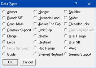
External forces and moments on the piping system in the global X, Y and Z directions may be input at any location. Type “fo” in the Data column or select “Force” from the Data Types dialog.
The Force dialog is shown.
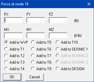
If you select “Add to W+P”, the specified forces and moments are applied to the sustained and operating load cases.
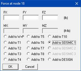
If you select “Add to SEISMIC 1”, the specified forces are applied to the Static Seismic Load case 1. Moments cannot be defined for the Static Seismic Load case and hence moment input fields are disabled.
Force defined in Global X direction (FX) will be included only with x’g solution when x’g acceleration input is non-zero. Similarly, forces defined in Global Y (FY) and Global Z (FZ) directions will be included in y’g and z’g solutions respectively, when y’g and z’g accelerations are input as non-zero values.
See Section titled “Static Seismic Load” from CAEPIPE User’s Manual for further details on how CAEPIPE performs Static Seismic Load analysis.
If you select any of the thermal cases (“Add to T1”, “Add to T2”, “Add to T3”, all the way up to “Add to T10”), the specified forces and moments are applied to the selected thermal load case (T1/T2/T3/…/T10) and its operating load case counterpart (i.e.,T1 and W+P1+T1, or T2 and W+P2+T2, or T3 and W+P3+T3 or T4 and W+P4+T4 or T5 and W+P5+T5 or T6 and W+P6+T6 or T7 and W+P7+T7 or T8 and W+P8+T8 or T9 and W+P9+T9 or T10 and W+P10+T10).