Nozzle Evaluation
One of the qualification requirements for a piping system is to keep the loads imparted by the piping on equipment nozzles within certain allowable limits. These loads consist of sets of three forces and three moments, for the various load combinations. There are basically two types of nozzle load limits: (1) nozzle loads applied to rotating equipment, and (2) nozzle loads applied to static equipment such as heat exchangers, tanks and vessels.
Nozzle Loads applied to rotating equipment
Rotating equipment consist of equipment with moving parts, such as pumps, compressors, turbines and fans. The pipe nozzle load limits are developed by the equipment manufacturer and are intended to prevent malfunction, such as shaft misalignment, or distortion of the casing that could impede the movement of impellers. These limits are typically based on actual testing of the equipment, and not on analysis.
Some pump standards have published standard nozzle load limits, but these are only valid for the particular pumps for which they are published. This is the case for the American Petroleum Institute’s API-610 and the Hydraulic Institute’s HI 9.6.2.11 standard.
See subsection titled “Pump” from this manual for more details.
Similarly, API 617 provides nozzle load limits for compressors and NEMA SM-23 for turbines.
See subsections titled “Compressor” and “Turbine” from this manual for further details.
Nozzle Loads applied to Fired Heaters and Air Cooled Heat Exchangers
API 560 provides nozzle load limits for Fired Heaters and API 661 for Air Cooled Heat Exchangers.
See subsections titled “Air Cooled Heat Exchanger” and “Fired Heater” from this manual for further details.
Nozzle Loads applied to static equipment
For Nozzles connected to static equipment such as heat exchangers, tanks and vessels, the pipe load limits are based on stress or strain limits at the nozzle-to-shell intersection, both on the shell and nozzle sides. At present, CAEPIPE considers pipe load limits based on stress or strain limits only at the shell side of the nozzle intersection.
Nozzle Evaluation Module
The Nozzle Evaluation module implemented in CAEPIPE computes Allowable Loads and Local Stresses at Shell for Nozzles connecting to Spherical and Cylindrical Vessels as per the following codes.
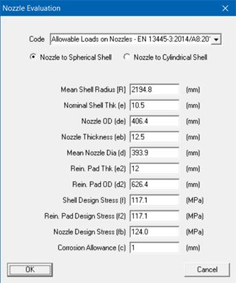
1. Allowable Loads on Nozzle – EN 13445-3:2014/A8:2019 (hereinafter referred as EN13445).
2. Local Shell Stresses at Nozzle– WRC Bulletin 537 (hereinafter referred as WRC 537).
3. Allowable Loads on Nozzle – HEI 2622 (2015) for Closed Feedwater Heaters (hereinafter referred as HEI 2622)
The Nozzle Evaluation module assumes that the flexibility analysis of that piping system with CAEPIPE has already been performed, which will have produced a stress report as well as the forces and moments at the location where the nozzle is attached to the piping.
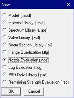
Note that this module is separate from a piping stress model file and can be accessed from File Menu > Open/New command.
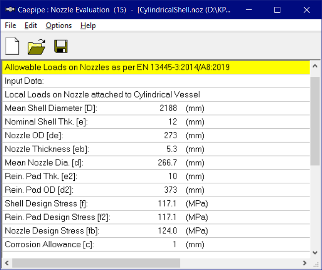
Double-clicking anywhere in the previous screen (or Edit menu > Edit (Ctrl+E)) opens a dialog with input fields you can edit. You will need to enter the data in this dialog. The different parameters required to be input are explained in detail below.
Details on implementation for Calculation of Local Shell Stresses at Nozzles as per WRC Bulletin 537 are provided in Code Compliance Manual.
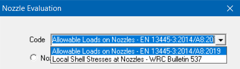
Code
Selecting the Code as “Allowable Loads on Nozzles – EN 13445-3:2014/A8:2019” or “Allowable Loads on Nozzles – HEI 2622 (2015)” will allow user to compute the “Allowable Loads on Nozzles”.
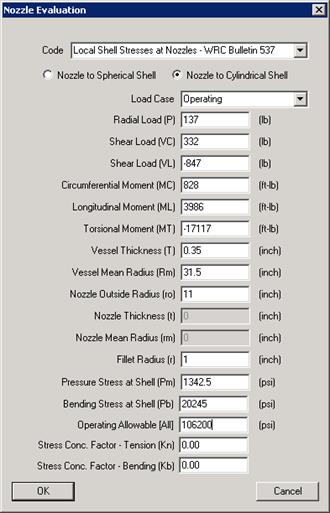
On the other hand, selecting the Code as “Local Shell Stresses at Nozzles – WRC Bulletin 537” will allow user to compute the Local Shell Stresses at Nozzles as per WRC 537 and perform Stress Compliance as per ASME Section VIII Division 2.
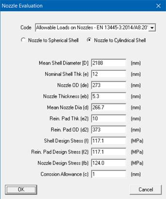
Nozzle to Spherical / Cylindrical Shell
Selecting the option “Nozzle to Spherical / Cylindrical Shell” will show the dialog boxes as shown below for the two Codes.
For EN13445, the input data required for the two types are shown below.
For HEI 2622, the input data required for Nozzle to Cylindrical Vessel is shown below.
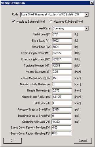
Similarly, for WRC 537, the data required to be input for the two types are shown below.
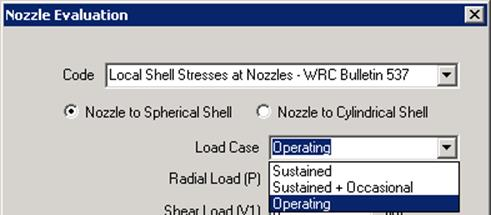
Load Case
From the option available, select the Load Case for which the three (3) forces and three (3) moments are being entered.

Depending upon the selection of “Load Case”, CAEPIPE will compute Radial/Circumferential, Tangential/Longitudinal, Shear and Combined Stress Intensities as explained below.
Please note, the display text for “Allowable (All)” input field will change automatically depending on the “Load Case” selected.
For example, for “Sustained” Load Case, the display text for “Allowable (All)” input field will change to “Sustained Allowable (All)”. Similarly for “Sustained + Occasional”, the display text will change to “Sustained + Occasional Allowable (All)”.
Sustained and Sustained + Occasional
Combined Stresses computed will exclude the following Bending Stresses from the Evaluation of Nozzle to Spherical / Cylindrical Shells respectively.
a. Radial/Circumferential Bending Stresses due to P
b. Radial/Circumferential Bending Stresses due to M1/MC
c. Radial/Circumferential Bending Stresses due to M2/ML
d. Tangential/Longitudinal Bending Stresses due to P
e. Tangential/Longitudinal Bending Stresses due to M1/MC
f. Tangential/Longitudinal Bending Stresses due to M2/ML
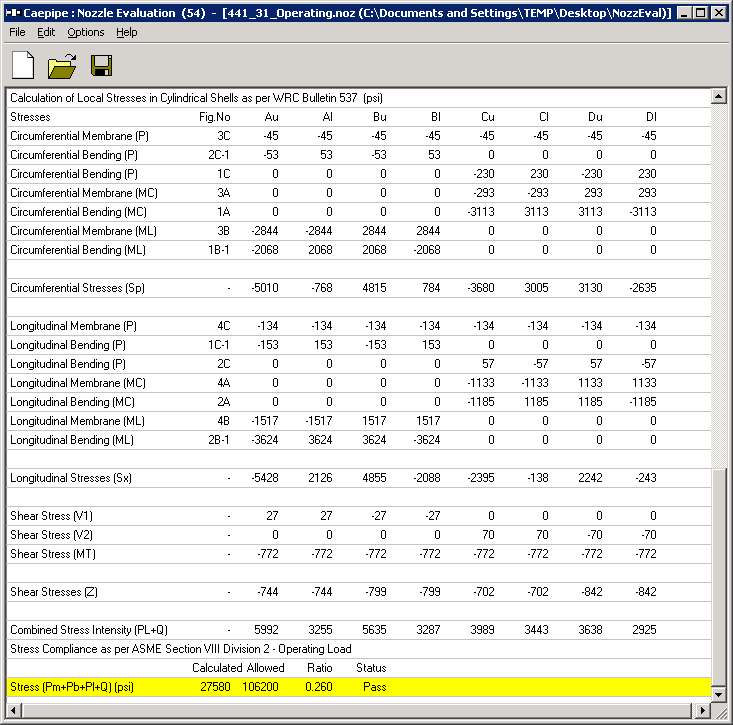
Operating
Combined Stresses computed will include all Membrane and Bending stresses due to P,M1 and M2 / P, MC and ML, Torsional stresses due to MT as well as Shear stresses due to V1/VC and V2/VL.
Once the required data are input, save the file (Nozzle evaluation will have a .noz extension). Now, select File menu > Analyze to calculate loads or stresses as per the code selected, which will be shown right below the input information.
Loads
For Nozzle to Spherical Vessel, enter the following loads computed in piping analysis for the selected load case.
1. Radial Load (P)
2. Shear Load (V1)
3. Shear Load (V2)
4. Overturning Moment (M1)
5. Overturning Moment (M2) and
6. Torsional Moment (MT)
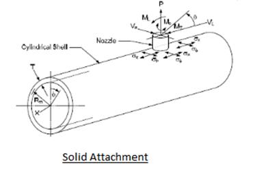
Similarly, for Nozzle to Cylindrical Vessel, enter the following loads computed in piping analysis for the selected load case.
1. Radial Load (P)
2. Shear Load (VC)
3. Shear Load (VL)
4. Circumferential Moment (MC)
5. Longitudinal Moment (ML) and
6. Torsional Moment (MT)
Vessel and Nozzle Parameters
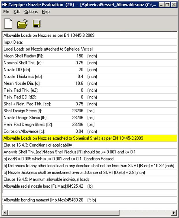
For Spherical Vessel, from the Vessel Drawing, read and enter the following parameters.
Vessel Thickness (T), Vessel Mean Radius (Rm), Nozzle Outside Radius (ro), Nozzle Thickness (t) and Nozzle Mean Radius (rm).
Similarly, for Cylindrical Vessel, from the Vessel Drawing, read and enter the following parameters.
Vessel Thickness (T), Vessel Mean Radius (Rm) and Nozzle Outside Radius (ro).
Fillet Radius
Fillet Radius is required to compute the Stress Concentration Factors for Tension (Kn) and Bending (Kb) from Figure B-2 WRC Bulletin 537.
Pressure Stress at Shell (Pm)
Pm is the Average Primary Membrane Stress across the cross-section of the vessel away from Gross Structural Discontinuities such as a Nozzle.
For a Spherical Shell such as Enclosure/Head to a Vessel, Pm due to internal pressure would be PR/2T,where P = Internal Pressure, R is the Mean Radius of the Head and T is the Thickness of the Head.
For a Cylindrical Shell such as Pressure Vessel/Pre-heater/Tank, to be conservative, Pm due to Internal Pressure would be the Circumferential Stress = PD/2T, where D is the Mean Diameter of the Cylinder.
The Stress value thus calculated should be entered in this field.
Bending Stress at Shell (Pb)
Pb is the Primary Membrane Stress proportional to the distance from the Axis of the Vessel due to External Loads such as Weight, Wind, Earthquake, etc. away from Gross Structural Discontinuities such as a Nozzle.
For a Spherical Shell such as Enclosure/Head to a Vessel, being a free end, Bending Stress Pb due to external loads could be 0.0.
For a Cylindrical Shell such as Pressure Vessel/Pre-heater/Tank, Bending Stress Pb due to external loads could be calculated as M/Z, where M is the Bending Moment on the Shell at Nozzle location and Z is the Section Modulus of the Shell.
So, Bending Stress Pb could be manually calculated or determined using computer programs.
Allowable Stress (All)
Allowable Stress (All) is to be computed and entered depending on the load case selected.
For example, as per Clause 5.2.2.4 of ASME Section VIII Division 2 (2017), the Allowable Stress (All) for both “Sustained” and “Sustained + Occasional” load case is to be entered as “1.5Sh”, where Sh is the basic allowable stress at maximum metal temperature for Shell.
Similarly, as per Clause 5.5.6 of ASME Section VIII Division 2 (2017), the Allowable Stress (All) for Operating load case should be entered as “3 (SC + Sh)/2 = 1.5 (SC + Sh)”, where Sc is the allowable stress at minimum metal temperature for Shell and Sh is defined above.
Stress Concentration Factors (Kn and Kb)
CAEPIPE will automatically compute the values of Kn and Kb using Figure B-2 of WRC 537 when these fields are entered as 0.0.
On the other hand, when these fields are entered with a value great than or equal to 1.0, then CAEPIPE will use these values of Kn and Kb while computing the stresses as per WRC 537.
Once the required data are input, save the file (Nozzle evaluation will have a .noz extension). Now, select File menu > Analyze to perform the evaluation, which will be shown right below the input information.
Nozzle Evaluation Module Menus
File Menu
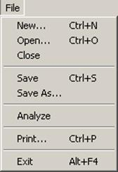
Analyze
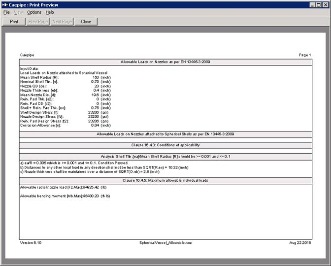
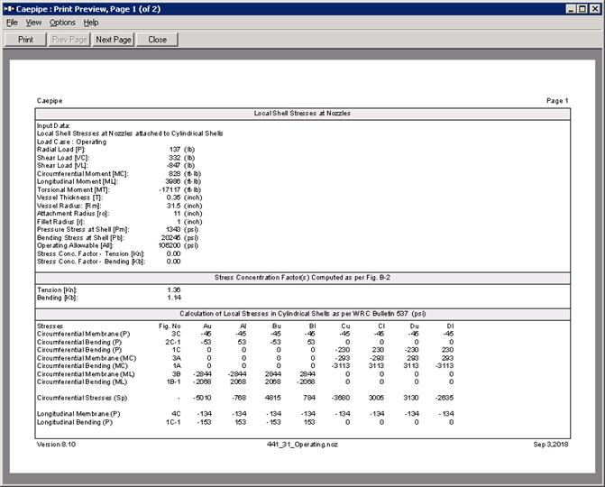
Analyze command calculates nozzle allowable loads as per EN 13445-3:2014/A8:2019 or shell stresses at the attachment as per WRC Bulletin 537 and compares them to stress allowable specified by ASME Section VIII Division 2 (2017).
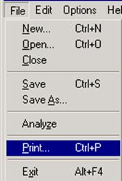
Print.
You can print a Report by using the Print command. You can also preview the report by clicking the Preview button on the print dialog.
Edit Menu
Edit
You can edit the data by clicking the Edit command.
Options Menu
Units
See Units in the Layout Window Options Menu section of the CAEPIPE User’s Manual.
Font
See Font in the Layout Window Options Menu section of the CAEPIPE User’s Manual.